Lighting device

Active Publication Date: 2016-12-08
CANON KK
View PDF2 Cites 0 Cited by
  • Summary
  • Abstract
  • Description
  • Claims
  • Application Information

AI Technical Summary

Benefits of technology

[0010]The present invention provides a lighting device capable of changing the light irradiation range that is capable of suppressi

Problems solved by technology

Doing so increases the size of the strobe device.
In addition, since the numb

Method used


Image

  • Lighting device
  • Lighting device
  • Lighting device

Examples


Example

[0027]An embodiment of the present invention will now be described with reference to the drawings. In each figure, the same components are given the same reference numerals, and redundant description thereof will be omitted.

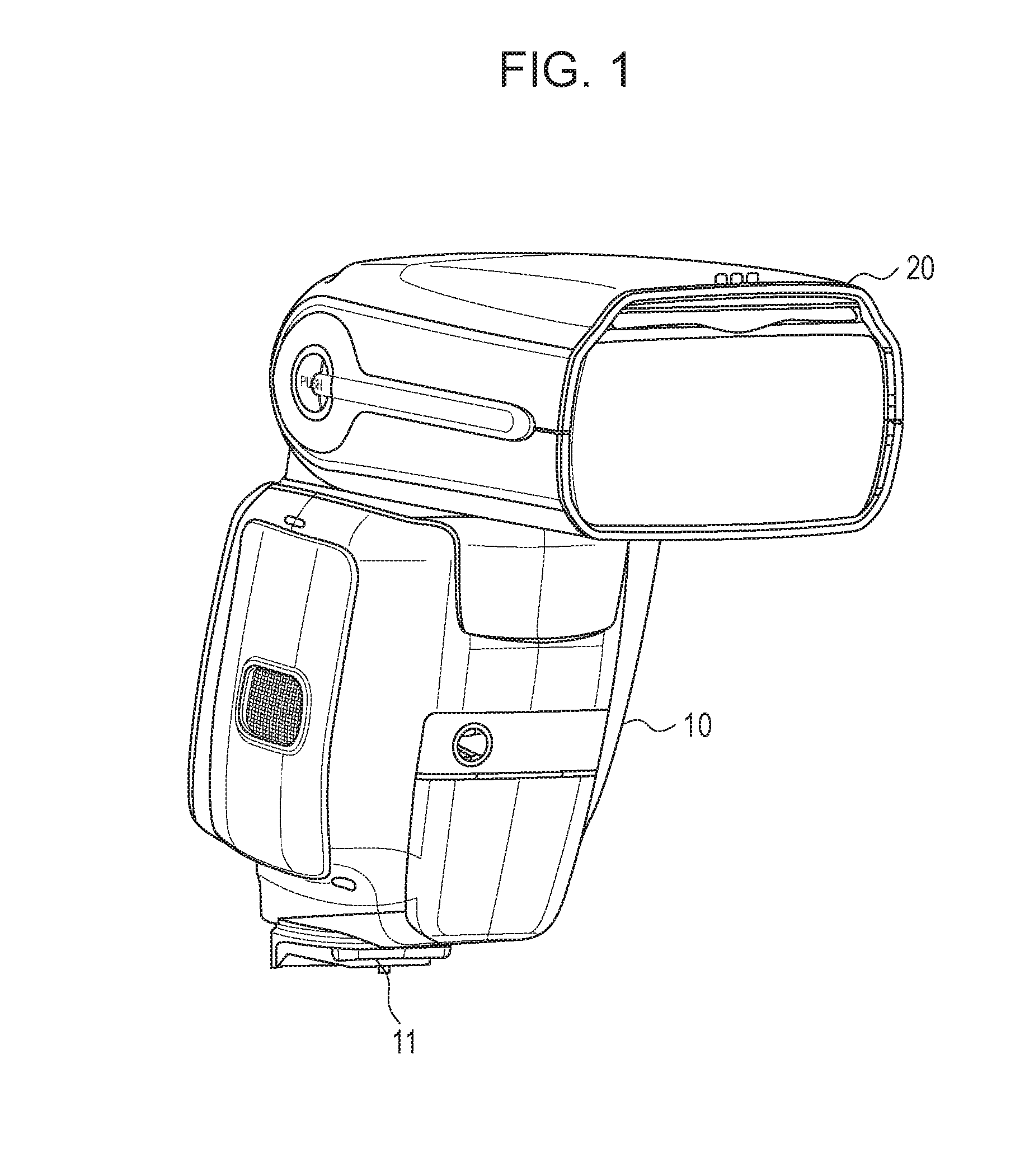
[0028]FIG. 1 illustrates a lighting device (hereinafter also referred to as a strobe device) detachable from a photographing device such as a digital camera. This strobe device consists of a mounting portion 11 for mounting on an accessory shoe of a photographing device, a main body 10 having a control circuit (not shown) and the like, and a movable portion 20 movable relative to the main body 10 and having a light emitting portion 21 and an optical panel 1 described later.

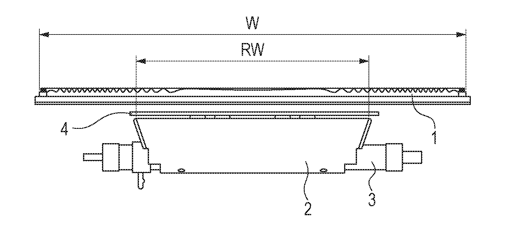
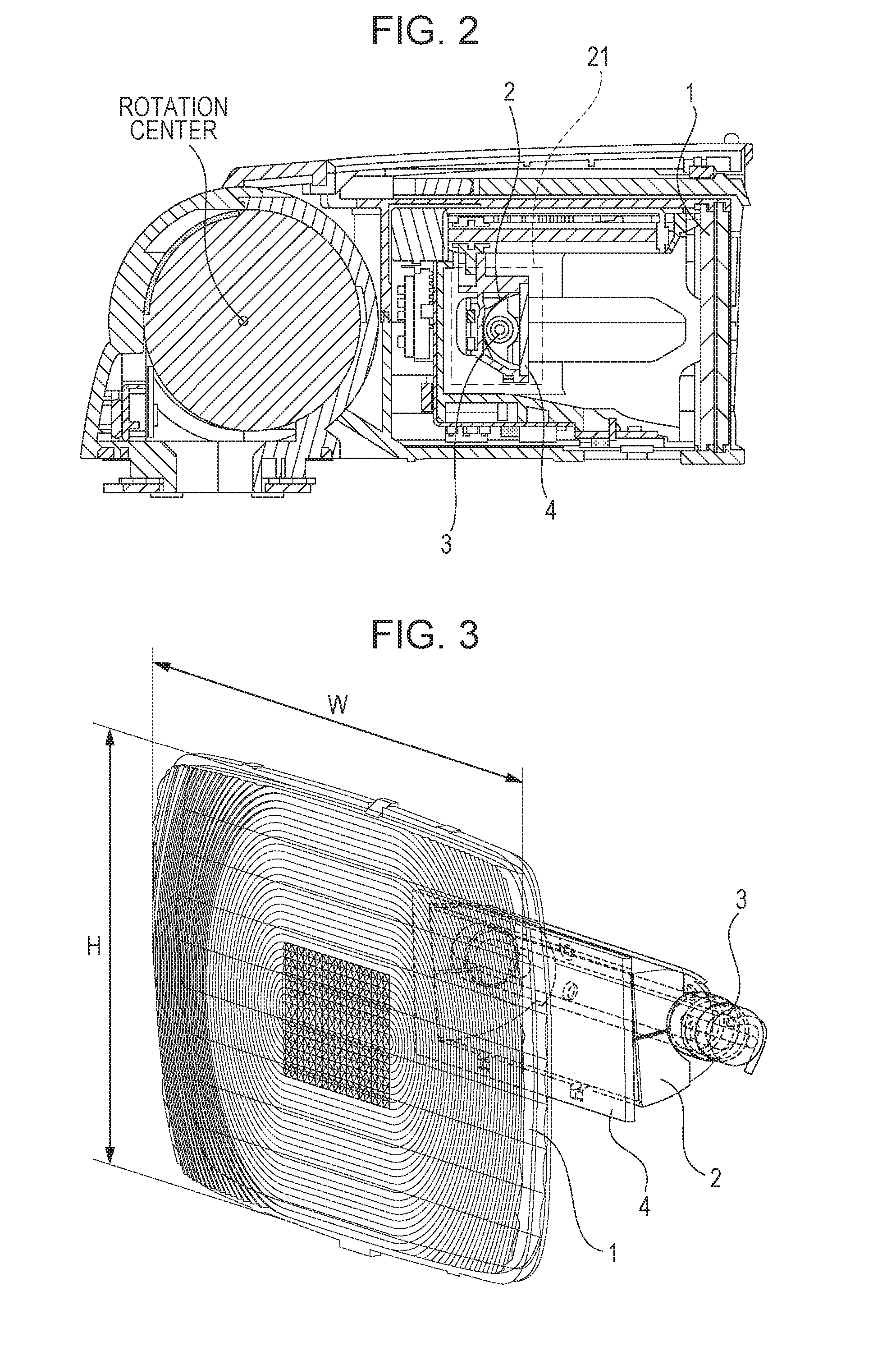
[0029]FIG. 2 is a sectional view perpendicular to the rotation center (axis of rotation) when vertically rotating the movable portion 20 relative to the main body 10, with the light emitting portion 21 moved to a position farthest from the optical panel 1 within a movable range (telephoto end s...


PUM


Abstract

A lighting device capable of changing the light irradiation range includes a light emitting portion, and an optical member disposed in front of the light emitting portion. The optical member has a plurality of shapes such that two types of cylindrical concave surface having axial directions substantially perpendicular to each other are crossed each other. The plurality of shapes are formed in a central region of an entry surface through which light from the light emitting portion enters or a central region of an exit surface through which the light entering through the entry surface exits.

Description

BACKGROUND OF THE INVENTION[0001]Field of the Invention[0002]The present invention relates to lighting devices capable of changing the light irradiation range.[0003]Description of the Related Art[0004]Heretofore, there have been known lighting devices capable of changing the light irradiation range (the irradiation range of the lighting devices) (hereinafter also referred to as zoom strobe devices). Some of such zoom strobe devices use a method in which the irradiation range is changed by changing the distance between a light emitting portion including a light source and a reflection umbrella reflecting light emitted from the light source and an optical panel disposed in front of the light emitting portion and refracting light from the light emitting portion. When using this method, for example, the irradiation range is widened by reducing the distance between the optical panel and the light emitting portion when performing wide-angle photographing, in which the angle of view is wid...

Claims


Application Information

Patent Timeline
IPC IPC(8): G03B15/05F21V7/04F21V5/04
CPCG03B15/05F21V5/045F21V7/04G03B2215/0592G03B2215/0567G03B2215/0578G03B2215/0514
Inventor OKANO, YOSHINOBU
Owner CANON KK
Why Eureka
Try Eureka