Enhanced coding and decoding using intra block copy mode

Active Publication Date: 2016-12-08
CANON KK
View PDF8 Cites 16 Cited by
  • Summary
  • Abstract
  • Description
  • Claims
  • Application Information

AI Technical Summary

Benefits of technology

[0013]Embodiments make it possible to extend the area for the block predictors, in particular when spatial subdivisions (e.g. slices and tiles) are u

Problems solved by technology

However, when slices or tiles are used in the

Method used


Image

  • Enhanced coding and decoding using intra block copy mode
  • Enhanced coding and decoding using intra block copy mode
  • Enhanced coding and decoding using intra block copy mode

Examples


Embodiment Construction

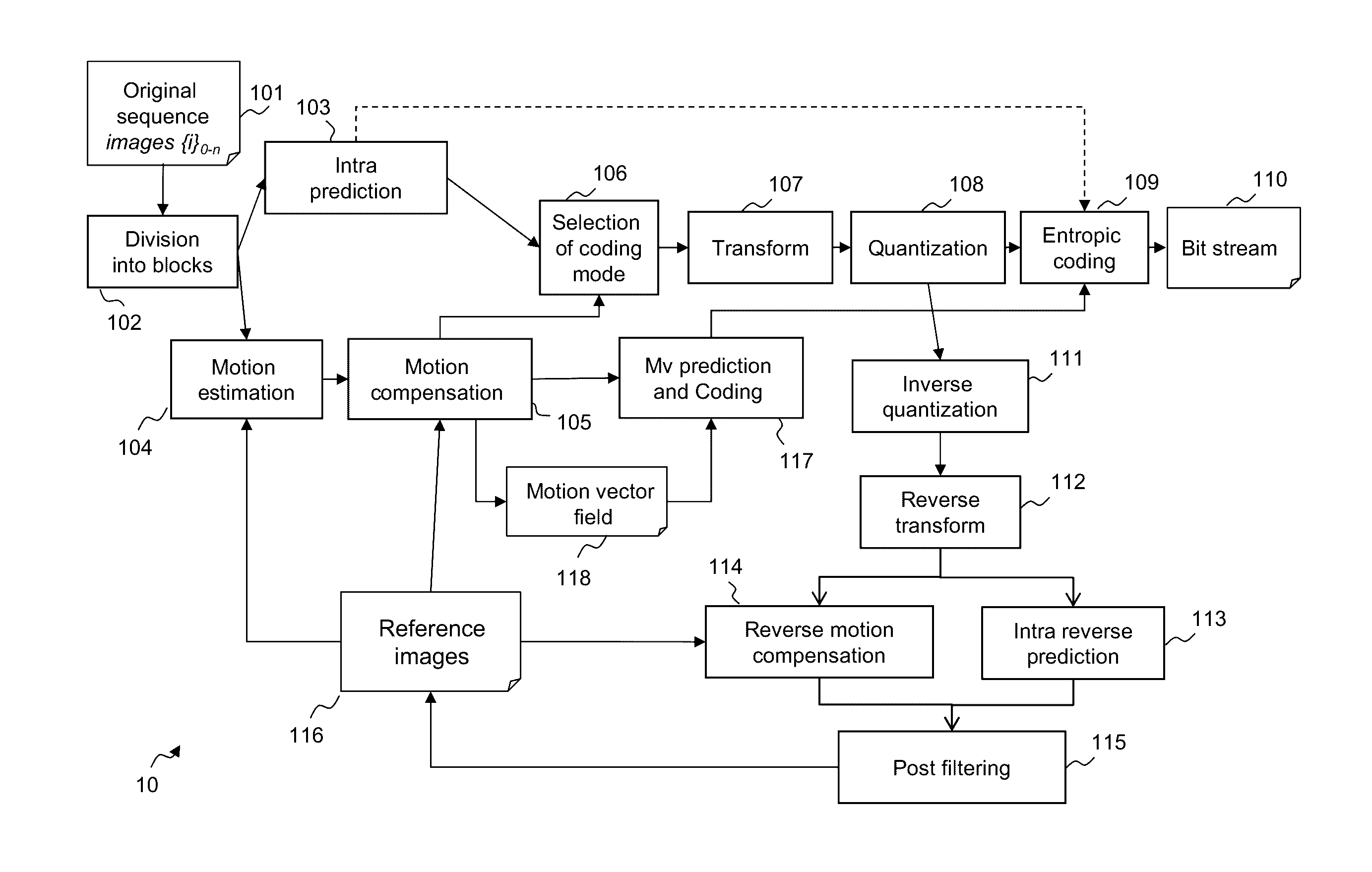
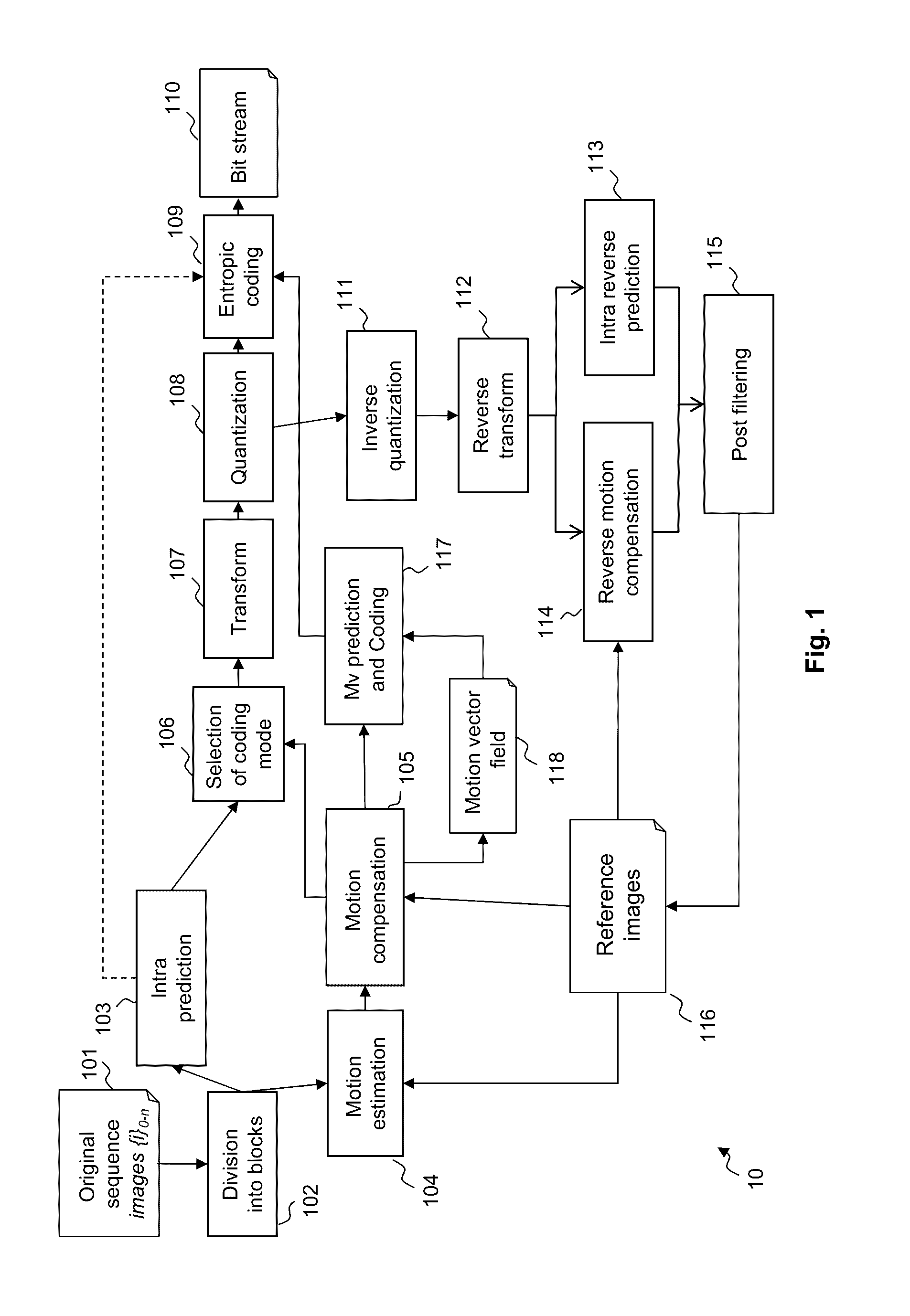
[0072]FIG. 1 illustrates the architecture of an HEVC encoder. An original sequence 101 is divided into blocks of pixels 102. A coding mode is then affected to each block.

[0073]Two families of coding modes are typically used according to the HEVC standard:[0074]the modes based on spatial prediction or INTRA modes 103, and[0075]the modes based on temporal prediction or INTER modes based on motion estimation 104 and motion compensation 105.

[0076]An INTRA Coding Unit is generally predicted from the encoded pixels at its “causal boundary” (defined in what follows) by a process called “INTRA prediction”.

[0077]Temporal prediction first comprises finding, in a motion estimation step 104, in a previous or future frame called the “reference frame”116, the reference area which is the closest to the Coding Unit. This reference area constitutes the predictor block.

[0078]Next, this Coding Unit is predicted using the predictor block to compute a residue in a motion compensation step 105.

[0079]In b...


PUM


Abstract

A decoding method wherein a motion vector is associated with a block of pixels of a current image,
    • wherein the image is subdivided into spatial subdivisions,
    • wherein the block of pixels belongs to a current spatial subdivision and is to be predicted using an Intra Block Copy mode, using a predictor block of pixels of the image designated by the motion vector, and
wherein the predictor block designated by the motion vector may belong to any one of previously decoded spatial subdivisions in the current image.
Embodiments provide enhancements to the Intra Block Copy Mode of the HEVC standard.

Description

[0001]This application claims the benefit under 35 U.S.C. §119(a)-(d) of United Kingdom Patent Application No. 1509930.2 filed on Jun. 8, 2015 and entitled “Enhanced coding and decoding using intra block copy mode.” The above cited patent application is incorporated herein by reference in its entirety.FIELD OF THE INVENTION[0002]The present invention relates to the encoding and the decoding of video data using the Intra Block Copy Mode.[0003]The Intra Block Copy (hereinafter IBC) mode is a prediction mode that has been added for the screen content coding of the HEVC standard.[0004]This prediction method is particularly well suited for extremely repetitive patterns. In particular, it is known to help coding graphical elements such as glyphs (i.e., the graphical representation of a character) or traditional GUI elements, which are very difficult to code using traditional intra prediction methods.[0005]Therefore, when encoding such data, IBC is largely selected and gives large gains fo...

Claims


Application Information

Patent Timeline
IPC IPC(8): H04N19/52H04N19/17H04N19/176H04N19/182
CPCH04N19/52H04N19/176H04N19/17H04N19/182H04N19/119H04N19/593
Inventor LAROCHE, GUILLAUMEGISQUET, CHRISTOPHEONNO, PATRICE
Owner CANON KK
Why Eureka
Try Eureka