Vehicle wheel

a technology of extending parts and wheels, applied in the field of vehicle wheels, can solve the problems of unlikely application of load to achieve the effects of reducing the weight of each of the one or more extending portions, improving the aerodynamic characteristics of the vehicle, and increasing the flexibility of the shape design

Inactive Publication Date: 2016-12-15
CENTRAL MOTOR WHEEL CO LTD
View PDF6 Cites 13 Cited by
  • Summary
  • Abstract
  • Description
  • Claims
  • Application Information

AI Technical Summary

Benefits of technology

[0007]The invention provides a technique that is effective for suppressing an increase in weight of a vehicle wheel and adjusting a flow of air in the vehicle wheel when a vehicle is traveling.
[0009]In the vehicle wheel having the above-described configuration, each of the one or more extending portions partially restricts a flow of air toward a vehicle inner side or a vehicle outer side through the opening portion. In addition, each of the one or more extending portions adjusts a flow of air on a surface of the extending portion. Thus, the aerodynamic characteristics of the vehicle can be improved. Further, in the above-described configuration, since each of the one or more extending portions is not connected to any of the hub portion and the plurality of spoke portions, even if a load is applied to the wheel when the vehicle is traveling, the load is unlikely to be applied to the one or more extending portions. Accordingly, it is possible to increase flexibility in design of the shape (plate thickness, orientation, size, and the like) of each of the one or more extending portions. As a result, the weight of each of the one or more extending portions can be reduced by reducing the plate thickness of the extending portion. This makes it possible to suppress an increase in the weight of the wheel. As described above, each of the one or more extending portions adjusts the flow of air toward the vehicle inner side or the vehicle outer side through the opening portion, and the flow of air on the surface of the extending portion, and thus, the aerodynamic characteristics of the vehicle can be improved. In this regard, since the flexibility in the design of each of the one or more extending portions is increased, the extending portion can be easily configured to have a shape that makes it possible to achieve desired aerodynamic characteristics of the vehicle and desired brake cooling performance. Thus, it is possible to provide the vehicle wheel that is effective for suppressing an increase in the wheel weight and adjusting the flow of air when the vehicle is traveling.
[0010]In the vehicle wheel according to the above-aspect of the invention, each of the one or more extending portions may extend from the wheel rim portion toward the hub portion without protruding beyond a vehicle outer side surface of each of the plurality of spoke portions in the cylindrical axis direction. With this configuration, it is possible to suppress contact (i.e., to reduce the possibility of contact) between each of the one or more extending portions of the wheel and an obstacle positioned outside the wheel (for example, a curb provided at a road shoulder as a boundary line between a roadway and a sidewalk or a safety zone).
[0011]Thus, according to the above-described aspect of the invention, it is possible to suppress an increase in the weight of the vehicle wheel and to adjust the flow of air in the vehicle wheel when the vehicle is traveling.

Problems solved by technology

Further, in the above-described configuration, since each of the one or more extending portions is not connected to any of the hub portion and the plurality of spoke portions, even if a load is applied to the wheel when the vehicle is traveling, the load is unlikely to be applied to the one or more extending portions.

Method used


Image

  • Vehicle wheel
  • Vehicle wheel
  • Vehicle wheel

Examples


Embodiment Construction

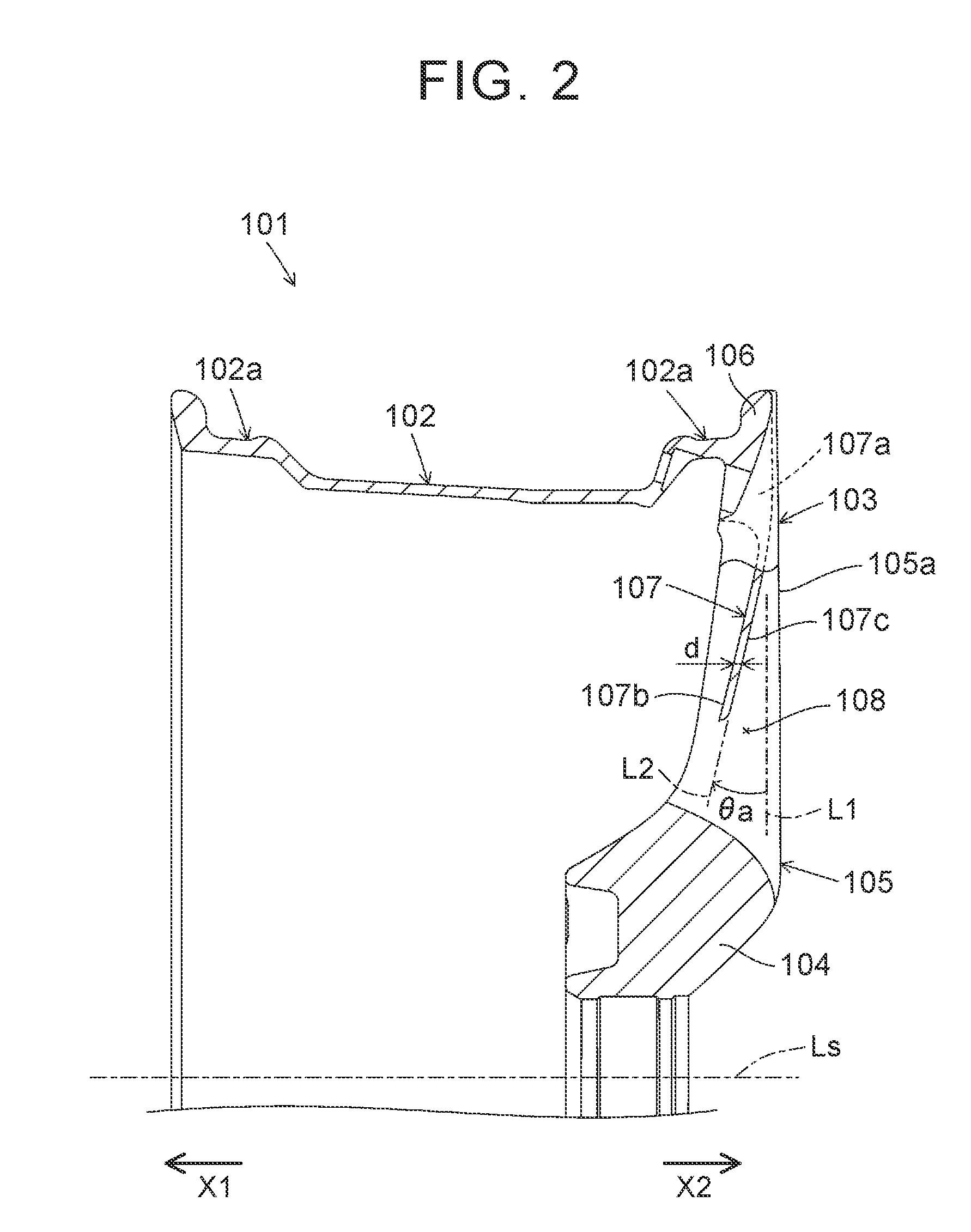
[0016]Hereinafter, a vehicle wheel (hereinafter, may be simply referred to as “wheel”) according to an embodiment of the invention will be described in detail with reference to the drawings. In FIG. 2, an arrow X1 indicates a vehicle inner side, and an arrow X2 indicates a vehicle outer side in a rim axis direction of a wheel rim portion constituting a part of the wheel.

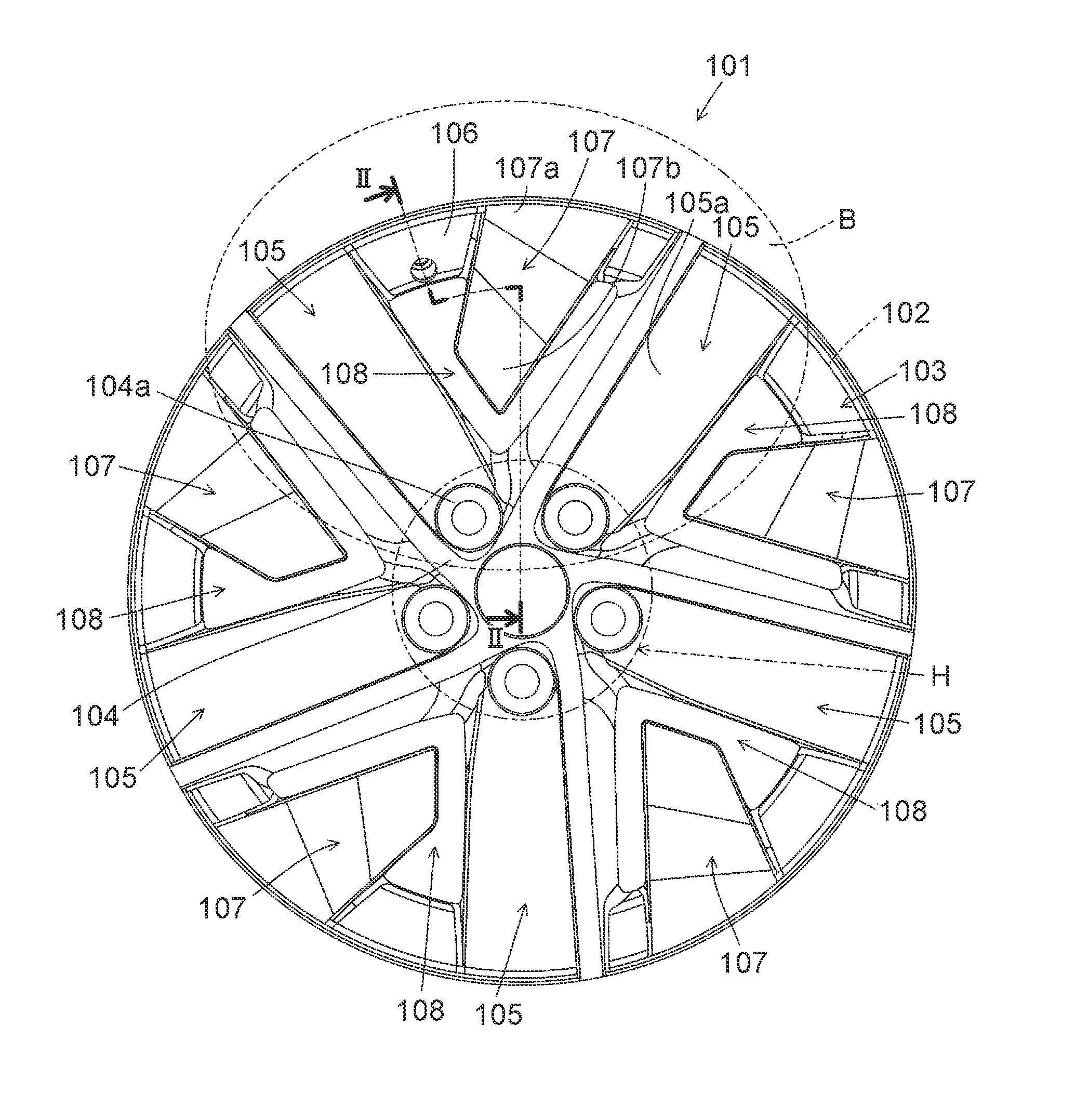
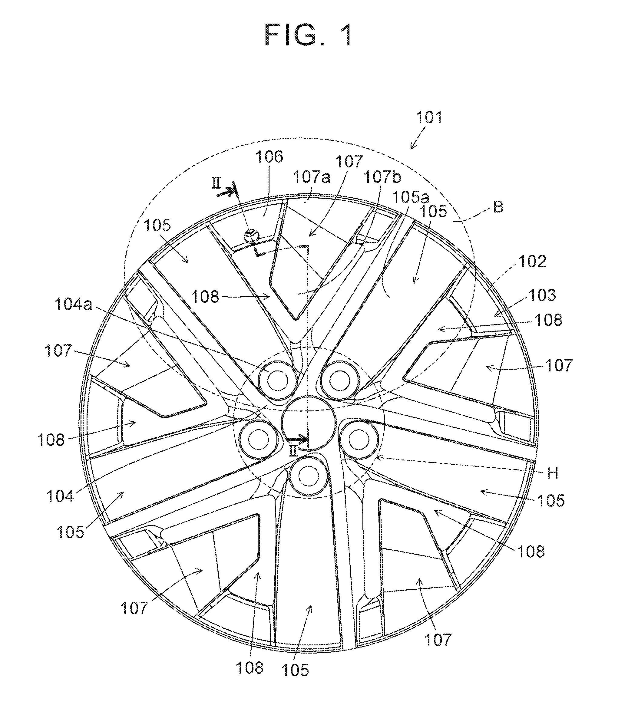
[0017]As shown in FIG. 1, a wheel 101 is a vehicle wheel (i.e., a wheel for a vehicle such as an automobile) to which an annular tire (not shown) is attached. The wheel 101 includes a wheel rim portion (hereinafter, may be simply referred to as “rim portion”) 102 and a wheel disc portion (hereinafter, may be simply referred to as “disc portion”) 103. The rim portion 102 has a cylindrical shape. The disc portion 103 has a disc shape and is integrally joined to a cylindrical end portion of the rim portion 102 on the vehicle outer side. The rim portion 102 includes a bead seat (i.e., a bead seat 102a in FIG. 2) that hol...


PUM


Abstract

A vehicle wheel includes a wheel rim portion; a hub portion; a plurality of spoke portions extending radially from the hub portion to the wheel rim portion and connected to the wheel rim portion; and one or more extending portions each of which is configured to partially cover an opening portion provided between two adjacent spoke portions among the plurality of spoke portions, and to extend from the wheel rim portion toward the hub portion without contacting any of the hub portion and the plurality of spoke portions, the one or more extending portions having a thickness that is smaller than a thickness of each of the plurality of spoke portions in a cylindrical axis direction of the wheel rim portion.

Description

INCORPORATION BY REFERENCE[0001]The disclosure of Japanese Patent Application No. 2015-118248 filed on Jun. 11, 2015 including the specification, drawings and abstract is incorporated herein by reference in its entirety.BACKGROUND OF THE INVENTION[0002]1. Field of the Invention[0003]The present invention relates to a vehicle wheel to which a tire is attached.[0004]2. Description of Related Art[0005]An example of this kind of vehicle wheel (hereinafter, may be simply referred to as “wheel”) is disclosed in each of Japanese Patent Application Publication No. 2003-048403 (JP 2003-048403 A) and EP Application Publication No. 2208621. In JP 2003-048403 A, a wheel cover, which is formed separately from the wheel, is attached to the wheel. The wheel cover includes an annular guide surface provided on the side of an outer periphery of the wheel. This cover shape is employed to ensure brake cooling performance, and to improve aerodynamic characteristics of a vehicle by adjusting a flow of ai...

Claims


Application Information

Patent Timeline
Patent Type & Authority Applications(United States)
IPC IPC(8): B60B1/06
CPCB60B1/06B60B2900/513B60B2900/111B60B3/007B60B3/02B60B3/04B60B3/085B60B3/10B60B7/0026B60B7/008B60B7/0086B60B21/02B60B2900/1216Y02T10/86Y02T10/88
Inventor IMAI, HIROSUKEYAMANO, HIROYUKIKATAOKA, NAOTOAMANO, TAKANORIKONDO, TETSUSHITAKEUCHI, SHINJI
Owner CENTRAL MOTOR WHEEL CO LTD
Why Eureka
Try Eureka