Aircraft structure and method of manufacture

a technology of aircraft and manufacturing methods, applied in the direction of air braking surfaces, wing adjustments, aircraft assembly, etc., can solve the problems of high manufacturing cost, large number of bespoke parts required, and difficult assembly of moving aerodynamic aircraft structures, etc., to achieve easy assembly, improve structural efficiency, and reduce manufacturing costs

Inactive Publication Date: 2016-12-15
AIRBUS OPERATIONS LTD
View PDF1 Cites 4 Cited by
  • Summary
  • Abstract
  • Description
  • Claims
  • Application Information

AI Technical Summary

Benefits of technology

[0017]Preferably, the aerodynamic surface component has a mating surface opposite to the aerodynamic external surface, the mating surface having an interface pattern on it corresponding to the frame structure of the structural component. This allows the aerodynamic surface component to be easily lined up with the structural component during manufacture. The interface pattern may be co-cured or co-moulded to the aerodynamic surface component.
[0018]Preferably, the mounting fixing is external to the frame and extends past the aerodynamic surface component such that it is not covered by the aerodynamic surface component. This allows the aircraft structure to be mounted to an aircraft without affecting the aerodynamic surface.
[0019]Preferably, the actuator fixing of the structural component is an internal part of the frame structure. This allows the force imparted by the actuator to be evenly distributed about the structural component, making it more structurally efficient.
[0020]Preferably, the structural component also comprises a sheet element on the other side of the frame structure to the aerodynamic surface component. This provides additional stiffness to the structural component.

Problems solved by technology

Moveable aerodynamic aircraft structures, such as spoilers, flaps, slats, ailerons, elevators and rudders, are particularly expensive to manufacture.
This results in a very large number of bespoke parts required.
Due to this large number of bespoke parts, the manufacture process is often largely manual to minimise the initial tooling required.
This increases the recurring cost of manufacturing the parts.
Whilst consideration has been given to using the same size and shape of spoilers, it has been found that this overly compromises the aerodynamic performance.

Method used


Image

  • Aircraft structure and method of manufacture
  • Aircraft structure and method of manufacture
  • Aircraft structure and method of manufacture

Examples


Embodiment Construction

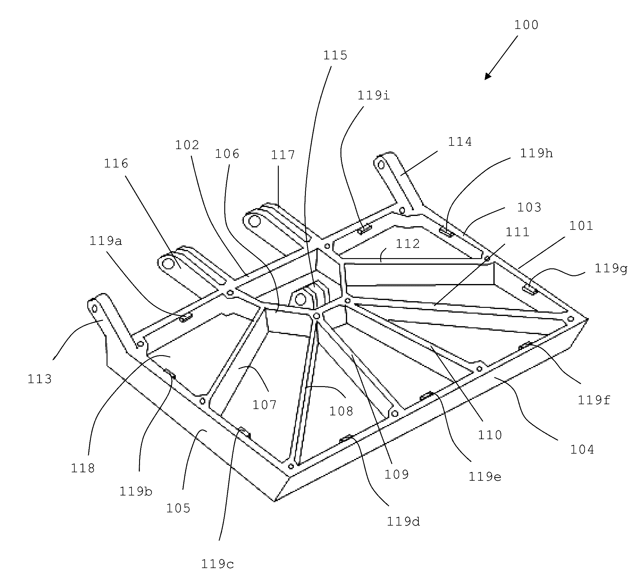
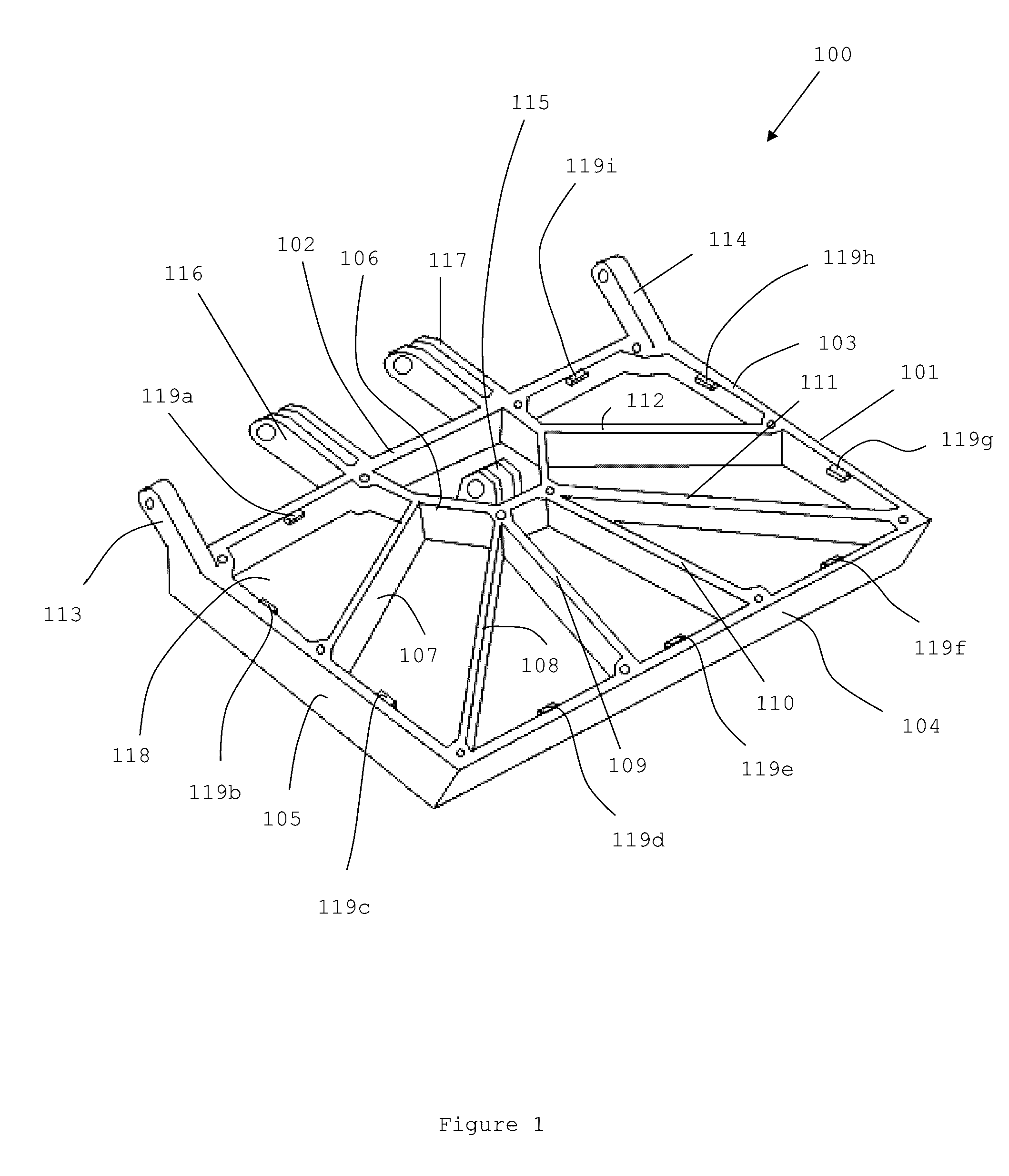
[0047]FIG. 1 shows a perspective view of a common structural module 100 for part of a spoiler. The common structural module 100 is intended to be used for all spoilers on an aircraft, with each spoiler having a different surface component (described later) attached to the common structural module 100.

[0048]The common structural module 100 comprises a rectangular box frame 101 with two short sides 103, 105 and two long sides 102, 104. Along the middle of one of the long sides 102 is a semi-circular frame 106 inside the box frame 101.

[0049]There are six struts 107, 108, 109, 110, 111, 112 radiating out from the semi-circular frame 106 to the insides of the sides 103, 104, 105 of the box frame 101. First strut 107 extends to approximately halfway along short side 105, second strut 108 extends to the corner of short side 105 and long side 104, third strut 109 extends to approximately a quarter of the way along the length of long side 104 from the corner with short side 105, fourth strut...


PUM


Abstract

The technology herein relates to an aircraft structure for being moveably mounted externally on an aircraft, the aircraft structure being an aerodynamic structure comprising a structural component providing structural strength and stiffness to the aircraft structure, the structural component comprising an integral fixing for moveably mounting the aerodynamic structure externally to the aircraft, and an integral fixing for attachment to an actuator for actuating movement of the aircraft structure with respect to the aircraft, and an aerodynamic surface component attached to one side of the structural component, the aerodynamic surface component providing an aerodynamic external surface of the aircraft structure. The technology herein also relates to a method of manufacturing the aircraft structure.

Description

BACKGROUND OF THE INVENTION[0001]The present invention concerns aircraft structures and methods of manufacture. More particularly, but not exclusively, this invention concerns an aircraft, structure for being moveably mounted. externally on an aircraft, the aircraft structure being an aerodynamic structure. The invention also concerns an aircraft with plurality of such aircraft structures and a method of manufacture of the aircraft structure(s).[0002]Moveable aerodynamic aircraft structures, such as spoilers, flaps, slats, ailerons, elevators and rudders, are particularly expensive to manufacture. This is especially the case for spoilers, where each spoiler on an aircraft has a slightly different shape, requiring different tooling to manufacture each spoiler and interface components. This results in a very large number of bespoke parts required. For example, a typical single-aisle aircraft may have 10 spoilers (5 spoilers on each wing). Due to this large number of bespoke parts, the...

Claims


Application Information

Patent Timeline
Patent Type & Authority Applications(United States)
IPC IPC(8): B64C3/58B64C9/32B64F5/00B64C9/34
CPCB64C3/58B64F5/0009B64C9/323B64C9/34B64C9/00B64C9/32B64F5/10
Inventor AXFORD, TIMOTHY
Owner AIRBUS OPERATIONS LTD
Why Eureka
Try Eureka