Light-emitting accessory

Inactive Publication Date: 2016-12-15
HAYASHI TELEMPU CO LTD
View PDF6 Cites 0 Cited by
  • Summary
  • Abstract
  • Description
  • Claims
  • Application Information

AI Technical Summary

Benefits of technology

The patent aims to provide a light emitting accessory that can evenly distribute light from a single light source. This invention helps to prevent uneven lighting on small numbers of light sources.

Problems solved by technology

According to the accessory product disclosed in JP Laid-open Patent Publication No. 2009-183327, since a plurality of LEDs are provided to illuminate entire portion of the accessory, there are some problems such as increased production cost, increased manufacturing process for assembling the LEDs, and increased size of the product for ensuring the space for installing the LEDs.
In addition, since the luminance of the accessory is extremely high at a LED-installed portion relative to the other portions, it is impossible to achieve homogeneous or uniform light emission from the entirety of the accessory product of JP Laid-open Patent Publication No. 2009-183327, regardless of the arrangement of the plurality of LEDs.
Therefore, it is impossible to achieve a homogeneous or uniform light emission from the entirety of the accessory.

Method used


Image

  • Light-emitting accessory
  • Light-emitting accessory
  • Light-emitting accessory

Examples


Embodiment Construction

[0031]In the following, an embodiment of the present invention will be explained with reference to the drawings.

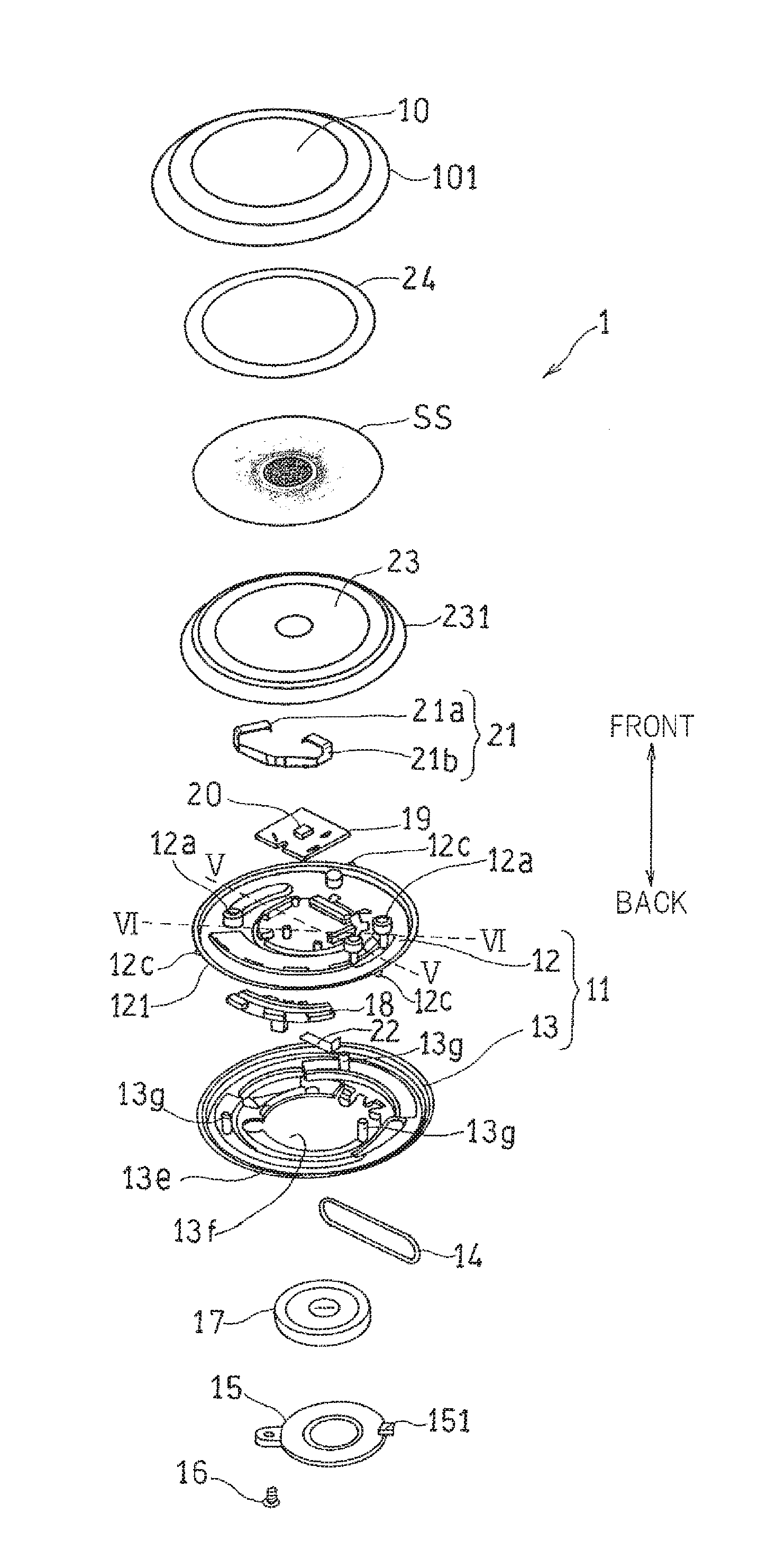
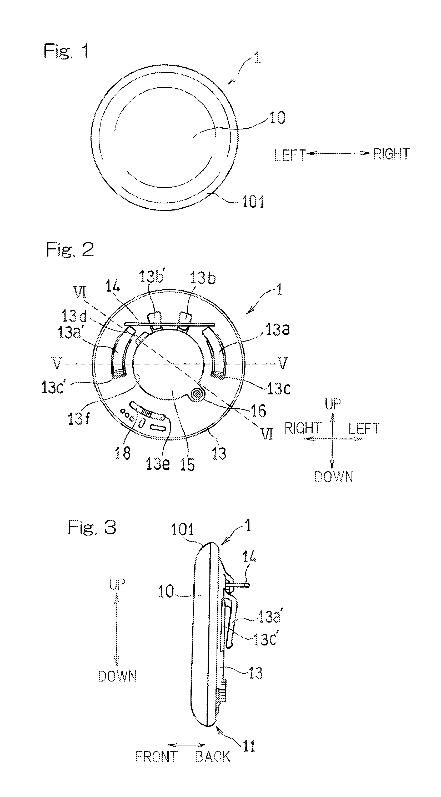
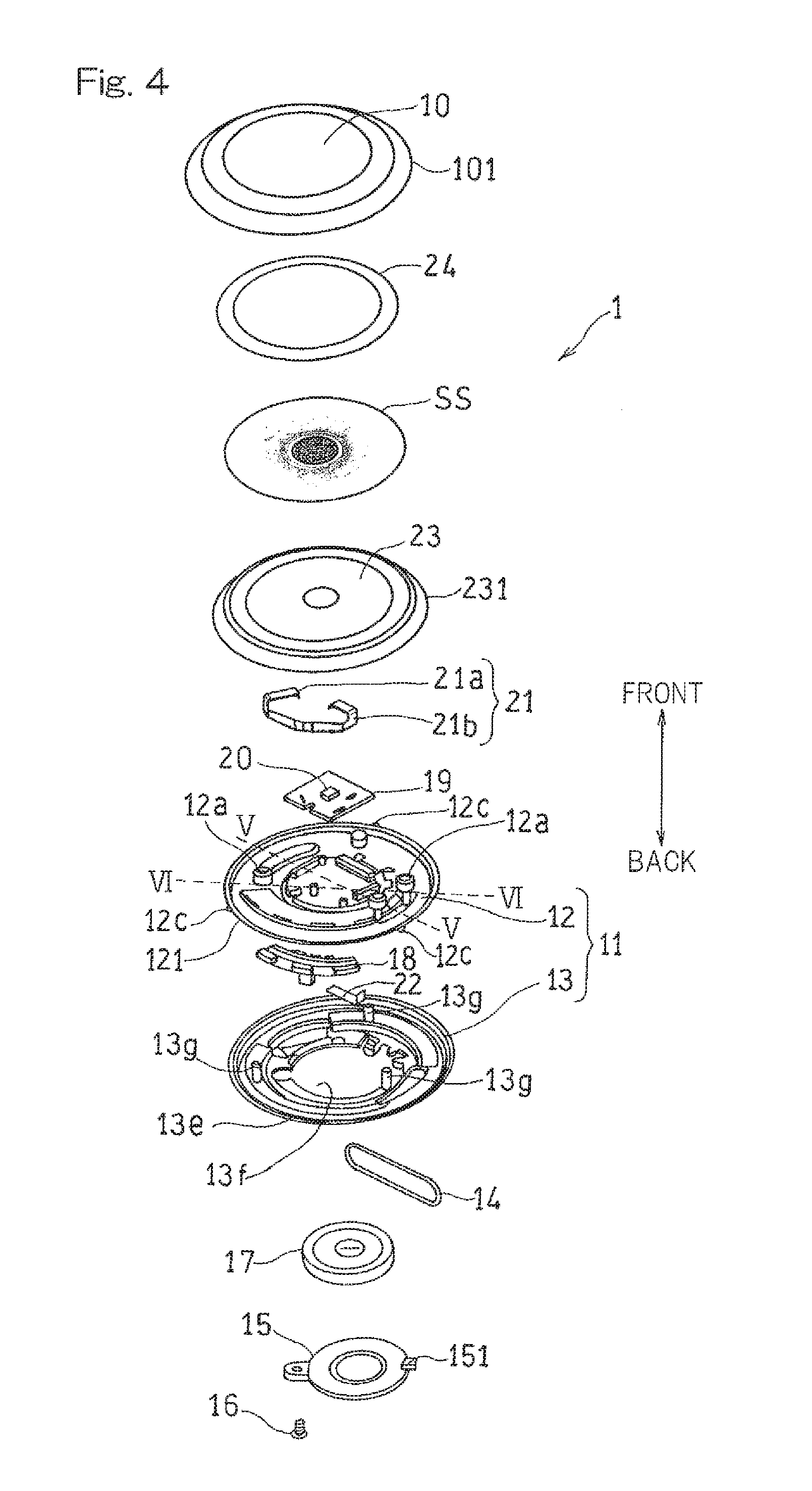
[0032]A front view of a badge 1 as an example of an light-emitting accessory according to an embodiment of the present invention is shown in FIG. 1, where the badge is observed from the side of a front surface of a light emitting plane. A rear view of the badge 1 observed from the side of a back surface opposite to the light emitting plane is shown in FIG. 2. A side view of the badge 1 observed from a lateral side (right side of FIG. 1) is shown in FIG. 3.

[0033]The badge 1 shown in FIG. 1 is made to have a (circular) disc shape of approximately 50 mm in diameter. A cover body 10 that constitutes a light emitting-plane also has the disc shape of the same dimension. As shown in FIG. 3, an outer peripheral portion 101 of the cover body 10 is formed to curve toward a back surface facing a case body 11 such that the portions 101 bulge to the radially outward direction. Specific...


PUM

PropertyMeasurementUnit
Thicknessaaaaaaaaaa
Shapeaaaaaaaaaa
Permeabilityaaaaaaaaaa

Abstract

A light-emitting accessory comprising: a light source; a light guide body that guides the light radiated from the light source; a case body that holds the light source and the light guide body and has an attachment to an outside thereof; a cover body formed by a light permeable material and being attached to the case body to cover the light source and the light guide body. The light guide body has a back surface facing the light source, and a front surface opposite to the back surface. In the vicinity of the center of the front surface is made an inclined portion which is inclined in a direction of thickness of the light guide body, and the light source confronts the inclined portion.

Description

CROSS-REFERENCE TO THE RELATED APPLICATION[0001]This application claims priority to Japanese Patent Application No. 2015-117408 filed on Jun. 10, 2015, the entire disclosure of which is herein incorporated by reference as a part of this application.FIELD OF THE INVENTION[0002]The present invention relates to accessories such as key-holders or key-rings, straps of cell phones, and badges attached to e.g., clothes, bags, and hats. Specifically, the present invention relates to accessories with a built-in light source capable of emitting light by lighting or flashing the light source.BACKGROUND ART[0003]Conventionally, light sources such as LEDs have been equipped inside accessories so as to emit light from a part of or a whole of the accessory such as badge by radiating light from the light sources. Light emission from the accessories has been performed for various purposes including a purpose of providing an illumination function to the accessories, or a purpose of lighting or flashi...

Claims


Application Information

Patent Timeline
IPC IPC(8): F21V33/00F21L4/00F21V23/04F21V8/00F21V3/04
CPCF21V33/0008G02B6/0065F21V3/0436G02B6/005F21W2121/06F21L4/00G02B6/0041F21Y2101/02F21V23/04A45C11/323F21S9/02F21Y2101/00F21Y2115/10A45C15/06F21V3/062G02B6/0046
Inventor MASE, TATSUOKAMEI, TADAYOSHIMATSUMOTO, TAKUYAKONISHI, HIROYOSHI
Owner HAYASHI TELEMPU CO LTD
Why Eureka
Try Eureka