Lamp

A flat part and light guide technology, applied in the field of lamps, can solve the problems of reducing the light utilization efficiency, unable to design the light emitting area of ​​the light guide element, and difficult to arbitrarily design the light emitting area of ​​the light guide element.

Inactive Publication Date: 2012-05-30
KOITO MFG CO LTD
View PDF4 Cites 0 Cited by
  • Summary
  • Abstract
  • Description
  • Claims
  • Application Information

AI Technical Summary

Problems solved by technology

In this area, since the LED element is usually covered so as to be hidden by the extension so as not to be exposed to the outside, the light that is allowed to illuminate the light guide element in the area where the light guide element is covered so as to be hidden by the extension blocked, whereby the light in this area becomes inefficient, thereby reducing the light utilization efficiency
In addition, when trying to design the lamp such that the second light source is placed behind the light guide member, and the light emitted by the second light source passes through the light guide member to be output to the front of the lamp, a part of the light guide member is covered so as to be When the extension is hidden, the light emission area of ​​the second light source is also limited by the extension, and the light utilization efficiency of the light emitted in the second light source is thus reduced
Therefore, when limiting the light emission area of ​​the light guide element, the light emission area of ​​the second light source needs to be considered, and it is difficult to arbitrarily design the light emission area of ​​the light guide element
In particular, it is not possible to design the light emitting area of ​​the light guiding element with smaller openings in the wall extensions

Method used


Image

  • Lamp
  • Lamp
  • Lamp

Examples


Embodiment Construction

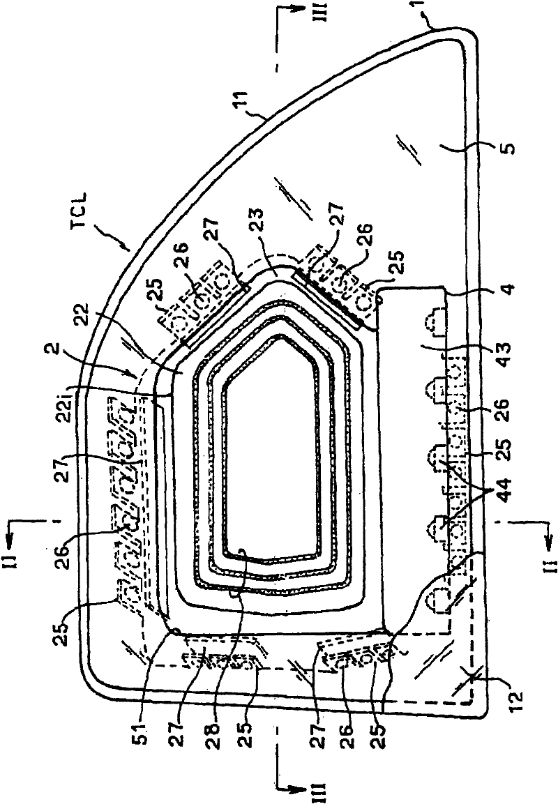
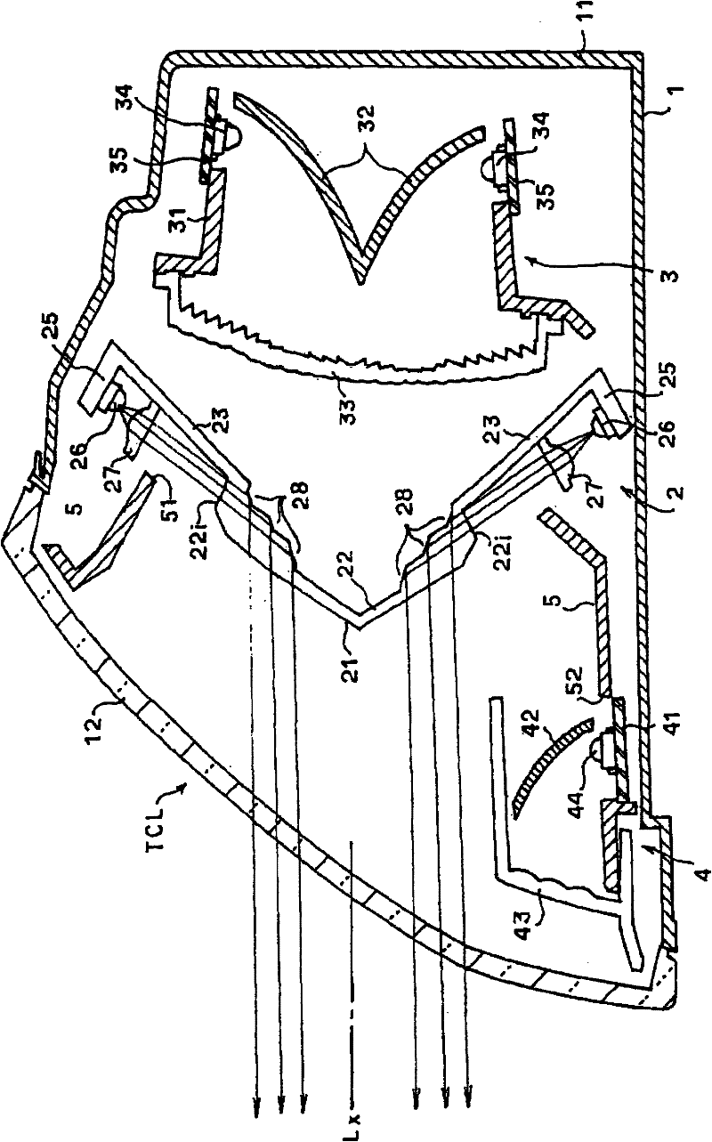
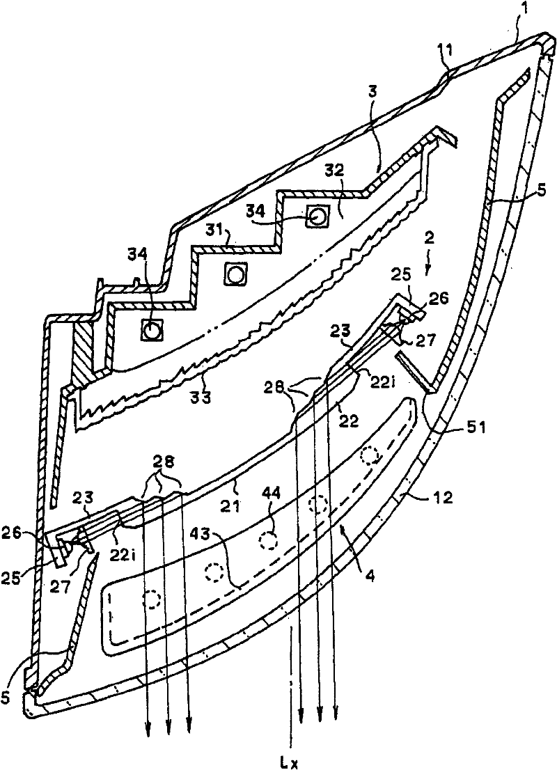
[0045] Exemplary embodiments of the present invention will be described. figure 1 is a front view of an exemplary embodiment in which the present invention is applied to a right-hand rear combination lamp TCL of a motor vehicle, figure 2 is along figure 1 Vertical cross-section taken along line II-II, image 3 is along figure 1 Horizontal cross-section taken along line III-III. In these figures, the lamp housing is defined by a lamp main body 11, which is mounted to the right-hand side of the rear of the motor vehicle body and is formed in a container shape, and a transparent front cover 12, the main body being on its front side (the motor vehicle's Open at the rear side), the front cover is attached to the front opening of the lamp main body 11 . The front cover 12 is formed in a shape inclined rearwardly at its upper portion in such a way as to match the raised shape of the vehicle body and is curved in the transverse direction in such a manner as to conform to the late...


PUM


Abstract

A lamp is provided with a light guiding element (21) and light sources (26). The light guiding element (21) includes: light incident planes (22i); reflecting plane portions (28); and light sources (26) for respectively emitting light to the light incident planes (22i). Light entered from the light incident planes (22i) into an interior of the light guiding element (21) is reflected on the reflecting plane portions (28) towards a front of the lamp for output. The light sources (26) respectively emit light to the light incident planes (22i). The light guiding element (21) is configured by a combination of a plurality of light guiding plane portions (22) which guide the light that has entered from the light incident planes (22i) towards the front of the lamp at different inclined angles.

Description

technical field [0001] The present invention relates to a lamp including a light guide element, and more particularly to a lamp that not only enhances the lamp utilization efficiency and lamp output efficiency when the light guide element and the light source are in the illuminated state, but also enhances the lamp when it is illuminated. design-related effects. Background technique [0002] In automotive lamps, lamps with light-guiding elements are provided as a design for enhancing the design-related effect of the lamp. For example, Patent Document 1 discloses a lamp in which a stepped reflective plane portion is formed at the back side of the light guide member so that the light that is allowed to enter the interior of the light guide member from the lower surface of the light guide member is guided through the light guide member. Light from the light element is reflected toward the front of the lamp on the reflective plane portion. In this lamp, since an illumination m...

Claims


Application Information

Patent Timeline
Patent Type & Authority Patents(China)
IPC IPC(8): F21S2/00F21V8/00F21V7/00
Inventor 平野旬一望月美希夏目和典六角屋裕之
Owner KOITO MFG CO LTD
Why Eureka
Try Eureka