
Backlight module and light source component thereof

A technology for light source components and light-emitting components, which is applied to electric light sources, light source fixing, and components of lighting devices, etc., can solve problems such as excessive light emission, and achieve the effect of uniform light emission.

Inactive Publication Date: 2011-07-06
CHI LIN OPTOELECTRONICS CO LTD
View PDF2 Cites 0 Cited by
  • Summary
  • Abstract
  • Description
  • Claims
  • Application Information

AI Technical Summary

Problems solved by technology

[0003] The purpose of the present invention is to provide a backlight module and its light source assembly to solve the problem of excessive light emission in some specific parts of the light-emitting area produced by the light-emitting assembly in the prior art

Method used


Image

  • Backlight module and light source component thereof
  • Backlight module and light source component thereof
  • Backlight module and light source component thereof

Examples


Embodiment Construction

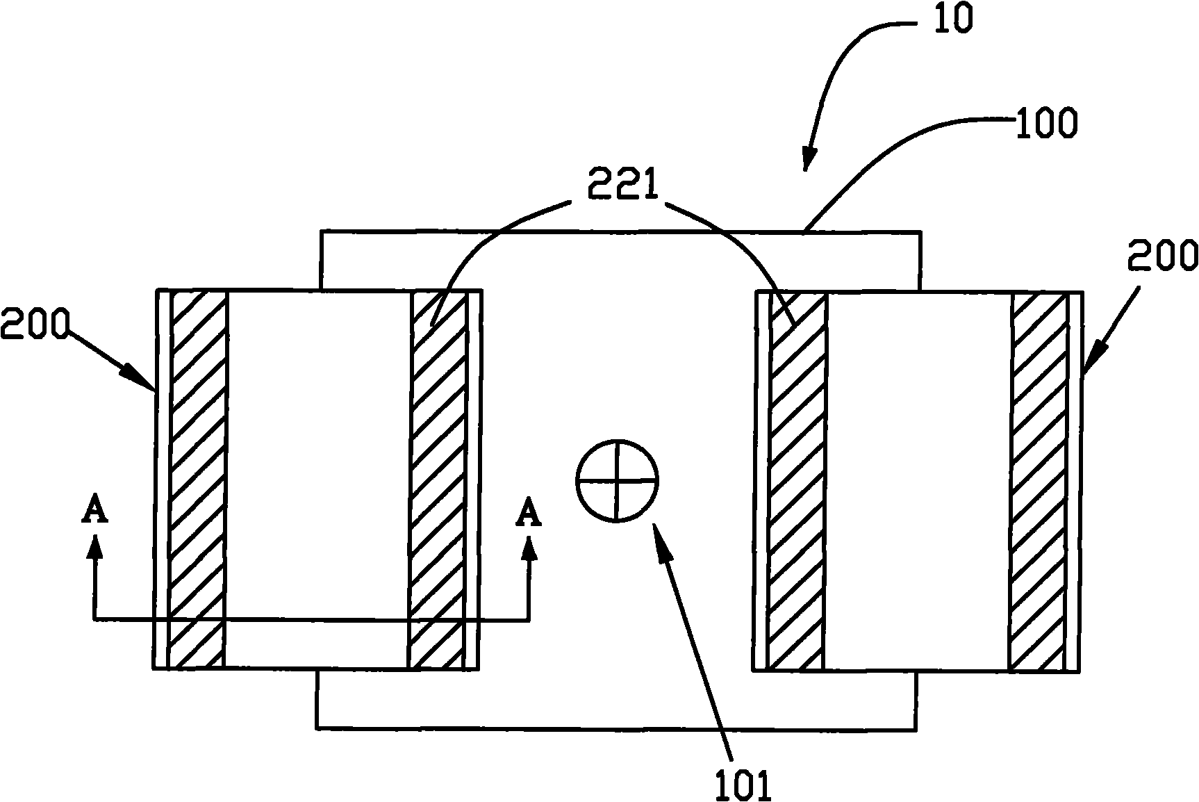
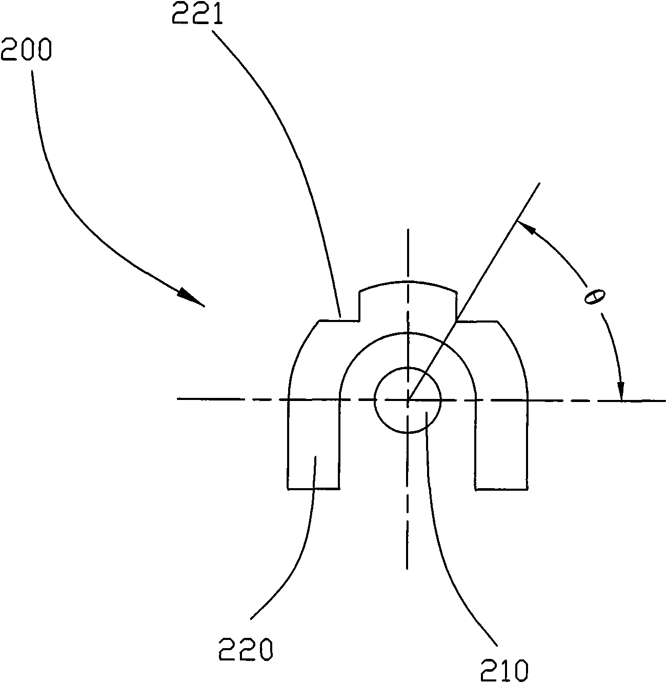
[0039] see Figure 1A and Figure 1B , Figure 1A is a schematic top view of a light source assembly according to an embodiment of the present invention, Figure 1B for along Figure 1A Schematic side view of the light source assembly in direction A-A. The light source assembly 10 of the present invention includes a frame-shaped area 100 and two light emitting devices 200 . The two light emitting devices 200 are located on two corresponding peripheries of the frame area 100 . The light emitting device 200 includes a light emitting component 210 and an optical component 220 , wherein the optical component 220 is disposed above the light emitting component 210 . In addition, the light emitting component 210 includes at least one light emitting diode (LED) or at least one cold cathode fluorescent lamp (CCFL). In this embodiment, the light emitting element 210 includes a cold cathode fluorescent lamp (CCFL).

[0040] Wherein, the above-mentioned frame-shaped area 100 defines a...


PUM


Abstract

The invention discloses a backlight module and a light source component thereof. The light source component comprises a frame type area and at least two light emitting devices, wherein the light emitting devices are located on the periphery of the frame type area and include one light emitting component and one optical component, and the optical component is arranged on the light emitting component; the frame type area has a geometric center, and the optical component is provided with at least one light arranging structure which faces to the geometric center. The backlight module comprises a plurality of optical films, the light source component and a framework set, wherein the light source component is arranged below the optical films, and the framework set is used for accommodating the plurality of optical films and the light source component. When the structure is adopted, the problem of excessive light emission produced in the whole light emitting area can be avoided, and the light emission quantity of the whole light emitting area can be more uniform.

Description

technical field [0001] The present invention relates to a light source assembly, in particular to a light source assembly with a light-rectifying structure, which can be used in a backlight module. Background technique [0002] At present, whether it is a light-emitting diode (LED) or a cold-cathode tube (CCFL) used in life or industry, the brightness of its light can meet the needs of the market. However, there is always a problem of excessive light emission in some specific parts of the light emitting area produced by light emitting diodes (LEDs) or cold cathode fluorescent lamps (CCFLs). Contents of the invention [0003] The purpose of the present invention is to provide a backlight module and its light source assembly, so as to solve the problem of excessive light emission in some specific parts of the light emitting area produced by the light emitting assembly in the prior art. [0004] According to the object of the present invention, a light source assembly is pro...

Claims


Application Information

Patent Timeline
Patent Type & Authority Applications(China)
IPC IPC(8): F21S8/00F21V17/10F21V19/00F21V5/00
Inventor 李一昌陈荣舜
Owner CHI LIN OPTOELECTRONICS CO LTD
Learn More