Optical light diffuser component having a substrate with optical structures and optical coatings and a method for manufacturing the same

a technology of optical structure and optical coating, applied in the field of light diffusers, to achieve the effect of high throughput, low cost and high efficiency of light diffusers

Inactive Publication Date: 2015-09-08
GREENLUX FINLAND
View PDF15 Cites 0 Cited by
  • Summary
  • Abstract
  • Description
  • Claims
  • Application Information

AI Technical Summary

Benefits of technology

[0007]It is an object of this invention to provide novel optical light diffuser component and a low cost and high through-put manufacturing method of highly efficient diffusers for lighting and particularly LED lighting applications. The invention also describes some examples of relevant materials that can be used for the manufacturing of the diffusers.
[0008]One particular aim of the invention is to provide a diffuser which increases light transmission from the light source toward the viewer.
[0009]Another aim of the invention is to provide a diffuser which creates uniform light emission from the LED lamp toward the viewer.

Problems solved by technology

For this reason, one of the main challenges is to be able to create a uniform diffused light from the LED lamps towards the viewer and the ambient and at the same time minimizing the LED amount in a lamp or lighting set.

Method used


Image

  • Optical light diffuser component having a substrate with optical structures and optical coatings and a method for manufacturing the same
  • Optical light diffuser component having a substrate with optical structures and optical coatings and a method for manufacturing the same

Examples


synthesis examples

MATERIAL SYNTHESIS EXAMPLES

High Refractive Index Material Synthesis Example (Metal Oxide Material)

[0045]600 grams of Titanium (IV) isopropoxide was placed to reactor flask. 470 grams of titanium tetrachloride was added to the reactor. 3760 ml of methanol was added to the reactor and stir the reaction solution for 2 hours. Methanol was distilled using membrane pump, distillation apparatus and oil bath. 2872 grams of 2-isopropoxyethanol was added to the material flask. Solution was allowed to cool down to −6° C. 1013 g of triethylamine was added in a way that the material solution temperature is kept between −6° C. and 6° C. during triethylamine addition. Solution was pre-filtrated using Buchner funnel. Solution continued to be cooled down in the reactor over night. Finally the solution was filtrated using a filter paper. Solution was formulated to the final processing solvent 2-isopropanol and was ready for processing after final filtration. When the synthesized material is coated an...

example 1

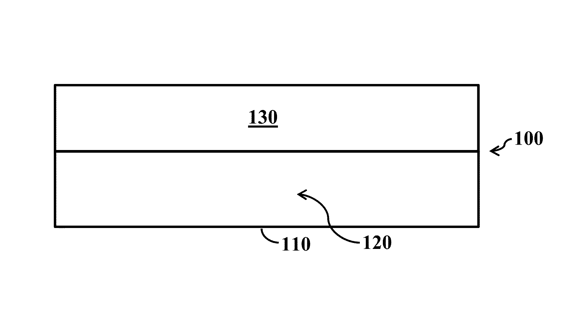
[0050]The substrate surface is patterned directly using for example embossing processing. The diffuser is cut to size from the larger substrate used in the embossing process or used as is. The cut substrate may be required to be deformed after cutting if some additional curvature or such is required to have in the diffuser.

example 2

[0051]The substrate surface is patterned directly using for example embossing and then coated (planarized or conformally coated) with a material layer. This material layer may give beneficial optical properties to the diffuser device or may have a mechanical protecting function. The diffuser is cut to size from the larger substrate used in the embossing process or used as is. The cut substrate may be required to be deformed after cutting if some additional curvature or such is required to have in the diffuser.


PUM


Abstract

An optical light diffuser component and a method of producing the same. The component includes at least one substrate material with an index of refraction of n1 and at least one optical coating on the substrate having an index of refraction of n2. The indices n1 and n2 are different. The optical light diffuser component produces uniform and diffuse light pattern from spot like light source, such as LED lamp, in terms of high optical transmission. The optical transmission is better than 90% at the visible spectrum of the light.

Description

BACKGROUND OF THE INVENTION[0001]1. Field of the Invention[0002]The present invention relates to light diffusers and to methods for manufacturing the same. In particular, the invention relates to diffusers, which have suitable properties for use in LED lighting applications. The invention also relates to a structure and manufacturing method of these diffuser structures. In addition, the invention relates to materials and methods used to produce the diffusers.[0003]2. Description of Related Art[0004]Light Emitting Diode (LED) typically consists of following parts / components: A semiconductor wafer: where the light emission is produced typically in form of UV light; LED cup wherein the LED wafer is mounted using typically a solder processing, wire-bonding and encapsulation; Encapsulate material wherein phosphorous mixed when considering white light LEDs. The encapsulate material is dispensed onto the LED chip and the cup. The encapsulate material can be for example a transparent silico...

Claims


Application Information

Patent Timeline
Patent Type & Authority Patents(United States)
IPC IPC(8): G02B5/02G02B5/00G02B5/18
CPCG02B5/0278G02B5/021G02B5/0252G02B5/001G02B5/1809G02B5/1847
Inventor BROMAN, MIKAELGORDON, GRAEMERANTALA, JUHA T.
Owner GREENLUX FINLAND
Why Eureka
Try Eureka