
Observation optical system, and image displaying apparatus having the same

a technology of optical system and image displaying apparatus, applied in the field of observation optical system, can solve the problems of impairing realism and affecting realism, and achieve the effects of wide field of view, easy reduction of aberration variation, and high optical performan

Active Publication Date: 2016-12-15
CANON KK
View PDF1 Cites 14 Cited by
  • Summary
  • Abstract
  • Description
  • Claims
  • Application Information

AI Technical Summary

Benefits of technology

The invention provides an observation optical system with high performance and a wide field of view that reduces aberration when the eye relief changes. Additionally, an image displaying apparatus utilizing this optical system is also provided.

Problems solved by technology

Because of this, the observation optical system has tended to increase field curvature and astigmatism in a wide field of view portion, and to impair the realism at the time when a pupil has been rotated.
However, the observation optical system in U.S. Pat. No. 9,104,019 does not necessarily sufficiently correct the lateral chromatic aberration and the field curvature, and also has tended to impair the realism at the time when the eye has rotated.

Method used


Image

  • Observation optical system, and image displaying apparatus having the same
  • Observation optical system, and image displaying apparatus having the same
  • Observation optical system, and image displaying apparatus having the same

Examples


exemplary embodiment 1

[0097]

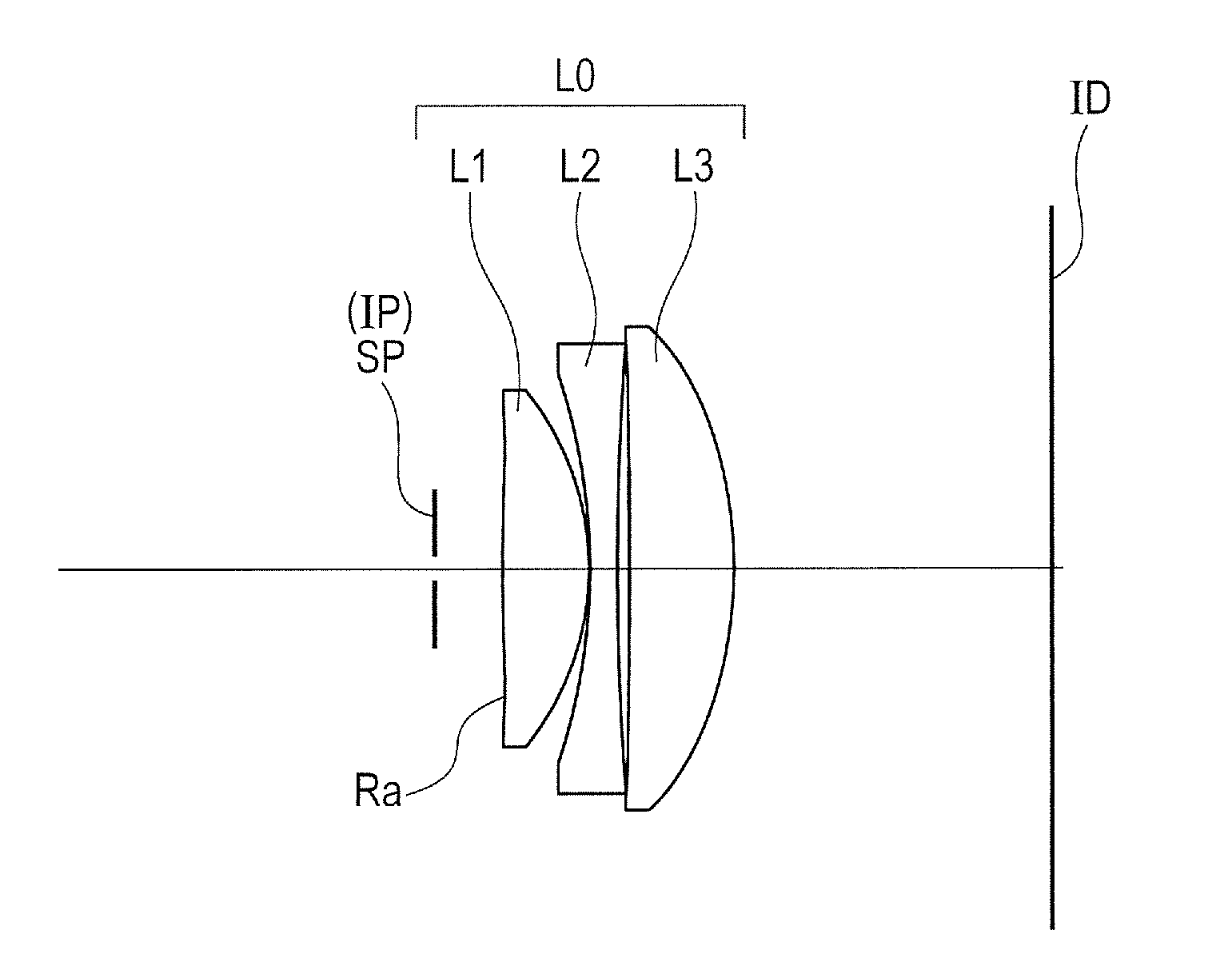
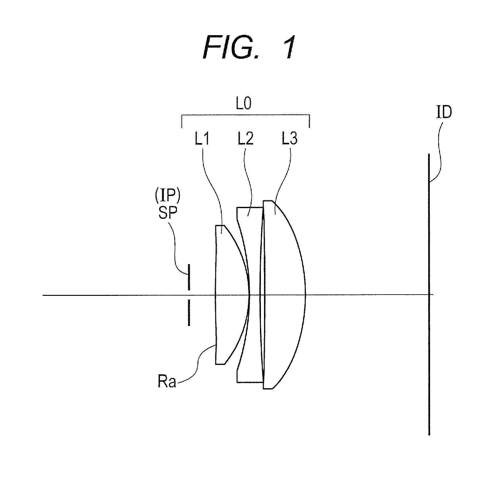
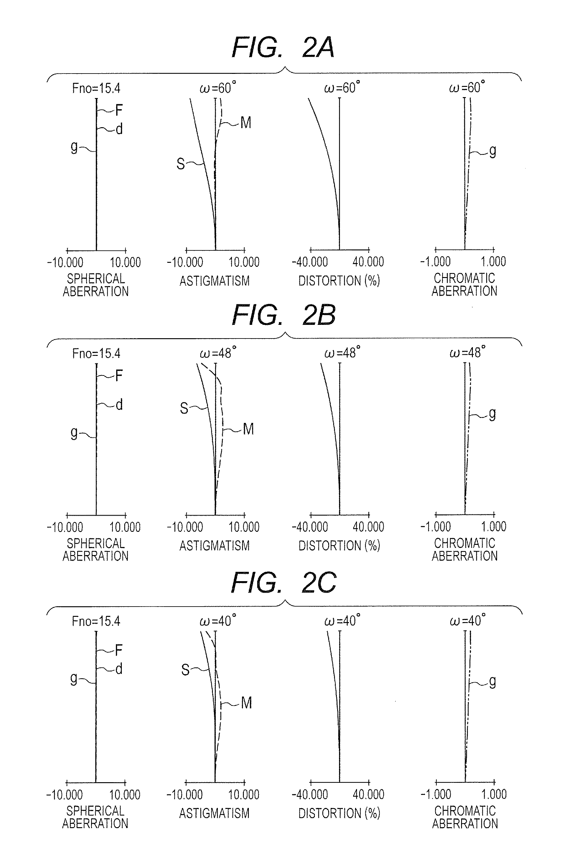
Unit mmSurface dataSurfaceEffectivenumberrdndνddiameter1 (Stop)∞(Variable)3.502*227.32112.751.6968055.546.103−41.5640.1551.004−89.2284.001.8466623.855.965443.0271.7464.726*−5614.70115.401.7725049.665.077*−65.143(Variable)69.68Image∞planeAspherical surface dataSecond surfaceK = 0.00000e+000A4 = −5.38982e−006A6 = 9.26789e−009A8 = −1.39354e−011A10 = 6.77348e−015Sixth surfaceK = 0.00000e+000A4 = 3.46712e−008A6 = 2.77586e−010A8 = −2.61351e−012A10 = 2.81884e−015A12 = −8.40445e−019Seventh surfaceK = 0.00000e+000A4 = 1.88792e−008A6 = −5.57207e−010A8 = −2.29416e−013A10 = −8.72376e−017Various dataEye relief10.0020.0026.00Focal length54.0054.0054.00F-number15.4315.4315.43Half angle of view44.6039.2934.74(degree)Image height53.2444.1937.44Total lens length90.79100.79106.79BF46.7546.7546.75d110.0020.0026.00d746.7546.7546.75Single lens dataLensLeading surfaceFocal lengthL1151.43L24−87.42L3685.21

exemplary embodiment 2

[0098]

Unit mmSurface dataSurfaceEffectivenumberrdndνddiameter1 (Stop)∞(Variable)3.502*285.56313.051.5315655.835.843−26.4870.1540.894*−34.4044.001.6355023.943.445−114.3851.0051.336*106.68517.641.5315655.861.087−60.000(Variable)64.00Image∞planeAspherical surface dataSecond surfaceK = 0.00000e+000A4 = 1.12503e−005A6 = −5.76267e−008A8 = 3.02125e−011A10 = −3.99871e−014Fourth surfaceK = 0.00000e+000A4 = −2.53346e−005A6 = 6.67721e−008A8 = −2.27478e−011Sixth surfaceK = 0.00000e+000A4 = 9.81955e−006A6 = −3.48881e−008A8 = 4.33651e−011A10 = −2.34247e−014A12 = 4.20163e−018Various dataEye relief10.0020.0026.00Focal length48.0048.0048.00F-number13.7113.7113.71Half angle of view39.3734.3527.64(degree)Image height39.3832.8125.14Total lens length84.5294.52100.52BF38.6738.6738.67d110.0020.0026.00d738.6738.6738.67Single lens dataLensLeading surfaceFocal lengthL1146.27L24−78.96L3675.00

exemplary embodiment 3

[0099]

Unit mmSurface dataSurfaceEffectivenumberrdndνddiameter1 (Stop)∞(Variable)3.50266.87512.711.8830040.838.943−44.7401.8641.054−35.0004.001.9228618.941.045−80.5750.1545.636*113.80711.991.5952267.748.397−50.000(Variable)50.35Image∞planeAspherical surface dataSixth surfaceK = 0.00000e+000A4 = −1.30020e−005A6 = 4.98066e−008A8 = −1.48622e−010A10 = 2.19300e−013A12 = −1.24019e−016Various dataEye relief10.0020.0026.00Focal length32.8032.8032.80F-number9.379.379.37Half angle of view38.0332.5627.72(degree)Image height25.6520.9417.23Total lens length62.4372.4378.43BF21.7221.7221.72d110.0020.0026.00d721.7221.7221.72Single lens data1LensLeading surfaceFocal lengthL1132.07L24−70.00L3660.00


PUM


Abstract

In order to obtain an observation optical system which has high optical performance while having a wide field of view, and can easily reduce variation of aberration at the time when an eye relief has changed, the present invention provides an observation optical system which is used for an observer to observe an image displayed on an image display surface, and includes in order from an observation side to an image displaying surface side: a first lens having a positive refractive power; a second lens having a negative refractive power; and a third lens having a positive refractive power, wherein a focal length f1 of the first lens, a focal length f2 of the second lens and a focal length f3 of the third lens are each appropriately set so as to satisfy the conditional expression of:0.40<f1-f2×f3<0.80.

Description

BACKGROUND OF THE INVENTIONField of the Invention[0001]The present invention relates to an observation optical system suitable for an image displaying apparatus such as a head mount display, which enlarges image information displayed on an image display surface of an image display element and provides the enlarged image information to an observer.Description of the Related Art[0002]Conventionally, an image displaying apparatus (head mount display or the like) is known which enlarges and displays image information that has been displayed with the use of the image display element such as CRT and LCD, through an observation optical system, and provides the realism of a picture to the observer. In recent years, it is desired for the image displaying apparatus which provides the realism to provide further high realism, and for this reason, an observation optical system which is used for the image displaying apparatus is required to correspond to a wide viewing angle and to have high opti...

Claims


Application Information

Patent Timeline
IPC IPC(8): G02B25/00G02B25/04G02B27/02G02B9/16
CPCG02B25/001G02B27/027G02B25/04G02B9/16
Inventor EBE, HIROKI
Owner CANON KK
Learn More