Combination antenna

Active Publication Date: 2016-12-15
SONY CORP
View PDF2 Cites 7 Cited by
  • Summary
  • Abstract
  • Description
  • Claims
  • Application Information

AI Technical Summary

Benefits of technology

The patent describes a combination antenna that includes a conductive block and a metallic housing. The conductive block has one or more electronic components mounted on its surface. The metallic housing is connected to the conductive block through one or more antenna feeds and one or more grounding points. The front surface of the metallic housing has plates separated by gaps, while the rear surface has a continuous plate separated from the front surface by a gap. The patent presents a general description of the illustrative embodiments and a detailed description of the teachings.

Problems solved by technology

As recognized by the present inventor, incorporating additional antennas to accommodate more frequency bands into electronic devices, such as Smartphones and tablets, becomes difficult due to space restrictions as well as increasing performances standards for the electronic devices.
In addition, users expect electronic devices to have a smooth and sleek design, which has led to electronic devices being manufactured with metallic outer surfaces, which may degrade the performance of the antennas.

Method used


Image

  • Combination antenna
  • Combination antenna
  • Combination antenna

Examples


Embodiment Construction

[0028]In the drawings, like reference numerals designate identical or corresponding parts throughout the several views. Further, as used herein, the words “a,”“an” and the like generally carry a meaning of “one or more,” unless stated otherwise. The drawings are generally drawn to scale unless specified otherwise or illustrating schematic structures or flowcharts.

[0029]Furthermore, the terms “approximately,”“about,” and similar terms generally refer to ranges that include the identified value within a margin of 20%, 10%, or 5%, and any values therebetween.

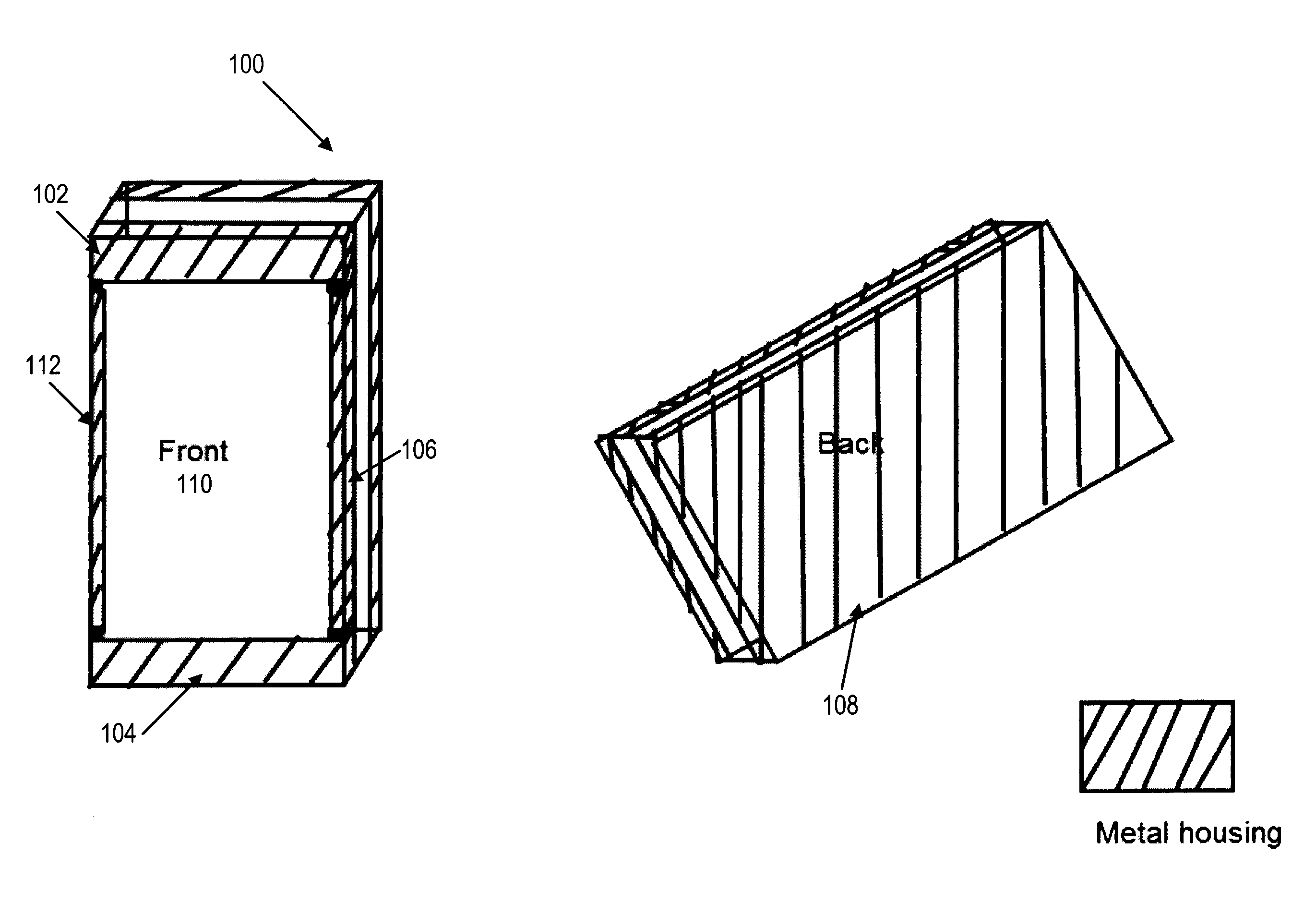
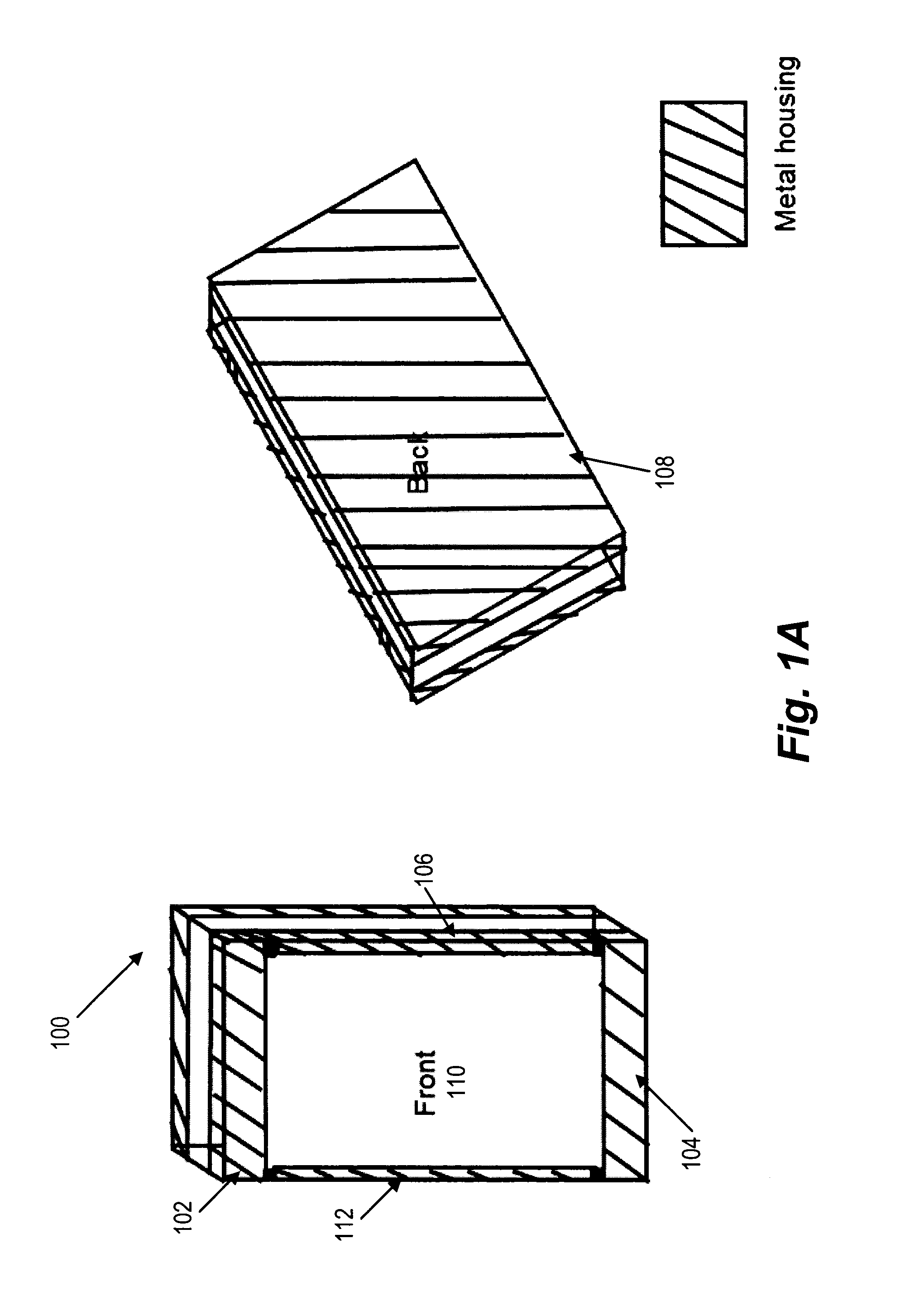
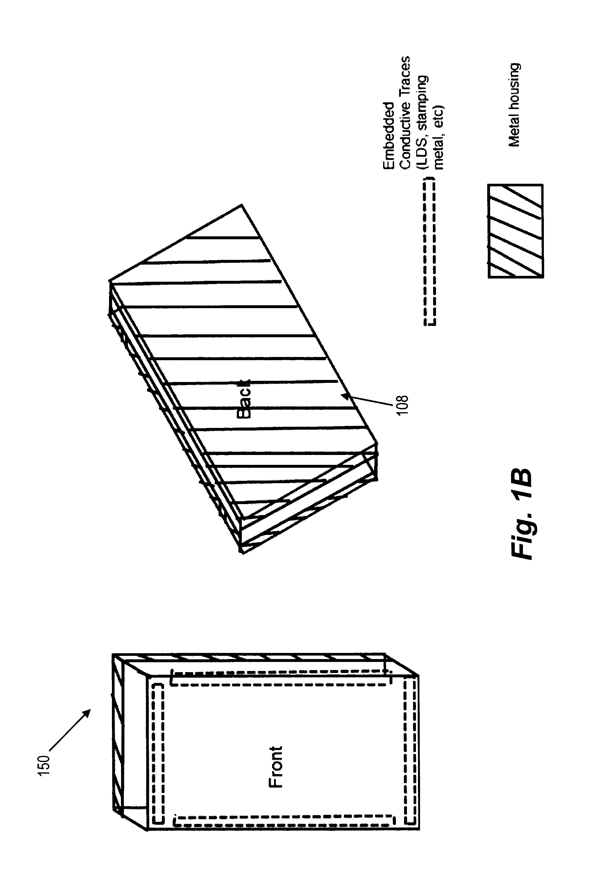
[0030]Aspects of the related disclosure are related to a combination antenna for electronic devices, such as SmartPhones, tablets, and the like, that incorporates one or more antenna feeds in order to function in a plurality of frequency ranges and incorporate or more wireless communication technologies. Examples of the wireless communication technologies include main cellular antennas, diversity cellular antennas, main and sub WIF...


PUM


Abstract

A combination antenna includes a conductive block having at least one electrical component mounted on the surface. A metallic housing is connected to the conductive block via at least one electronic element having a front surface and a rear surface. The front surface includes one or more plates separated by gaps of a predetermined width. The rear surface includes a continuous plate separated from the front surface by a gap of a second predetermined width. One or more antenna feeds are disposed between the front surface and the rear surface of the metallic housing and are connected to the metallic housing directly or via the at least one electronic element. A grounding plane includes one or more grounding points connected to the front surface and the rear surface directly or via the at least one electronic element.

Description

BACKGROUND[0001]Field of Disclosure[0002]This disclosure relates to a combination antenna for electronic devices, such as SmartPhones, tablets, and the like, that incorporates one or more antenna feeds in order to function in a plurality of frequency ranges and incorporate one or more wireless communication technologies.[0003]Description of the Related Art[0004]The “background” description provided herein is for the purpose of generally presenting the context of the disclosure. Work of the presently named inventors, to the extent it is described in this background section, as well as aspects of the description which may not otherwise qualify as prior art at the time of filing, are neither expressly or impliedly admitted as prior art against the present invention.[0005]As recognized by the present inventor, incorporating additional antennas to accommodate more frequency bands into electronic devices, such as Smartphones and tablets, becomes difficult due to space restrictions as well...

Claims


Application Information

Patent Timeline
IPC IPC(8): H01Q1/24H01Q1/50H01Q1/48H02J7/02
CPCH01Q1/243H01Q1/48H01Q1/50H02J7/025H01Q21/28H01Q21/30H01Q5/328H01Q5/335H01Q5/35H01Q7/00H02J50/20
Inventor YONG, CHECK CHIN
Owner SONY CORP
Why Eureka
Try Eureka