
Data Transmission Arrangement, Data Receiver, and Method for the Operation Thereof

a data transmission and data receiver technology, applied in transmission, power management, network traffic/resource management, etc., can solve the problems of data packet interference and inability to supply constant energy, and achieve the effect of reducing transmitting power and reducing transmitting power

Active Publication Date: 2016-12-15
FRAUNHOFER GESELLSCHAFT ZUR FOERDERUNG DER ANGEWANDTEN FORSCHUNG EV
View PDF2 Cites 22 Cited by
  • Summary
  • Abstract
  • Description
  • Claims
  • Application Information

AI Technical Summary

Benefits of technology

The patent describes a data transmission arrangement and a data receiver that can transmit and receive data packets with a time delay using a communication channel. The data transmission arrangement includes an energy supplier, a determiner, a coder, a splitter, and a transmitter. The energy supplier provides energy to the arrangement, and the energy is used to power the transmitter. The transmitter uses a time-consuming process to determine which data packets to transmit. The data receiver measures the energy of the received data stream and uses a time-consuming process to determine which data packets to process. The technical effect of this invention is to improve the efficiency of data transmission and reduce the amount of energy needed for transmission.

Problems solved by technology

In data transmitters which draw their energy from the environment via an energy harvesting method, e.g. via light, temperature differences or vibrations, for example, a constant supply of energy may not be possible in some circumstances.
In the transmission of the data packets via a communication channel from the data transmission arrangement that is self-sufficient in terms of its energy supply to a data receiver, the data packets may be interfered with, for example by noise or by other data transmitters which simultaneously transmit data packets within the same or a similar frequency band.

Method used


Image

  • Data Transmission Arrangement, Data Receiver, and Method for the Operation Thereof
  • Data Transmission Arrangement, Data Receiver, and Method for the Operation Thereof
  • Data Transmission Arrangement, Data Receiver, and Method for the Operation Thereof

Examples


Embodiment Construction

[0038]In the subsequent description of the embodiments of the invention, elements that are identical or have identical actions will be referred to by identical reference numerals in the figures so that their descriptions within the different embodiments are mutually exchangeable.

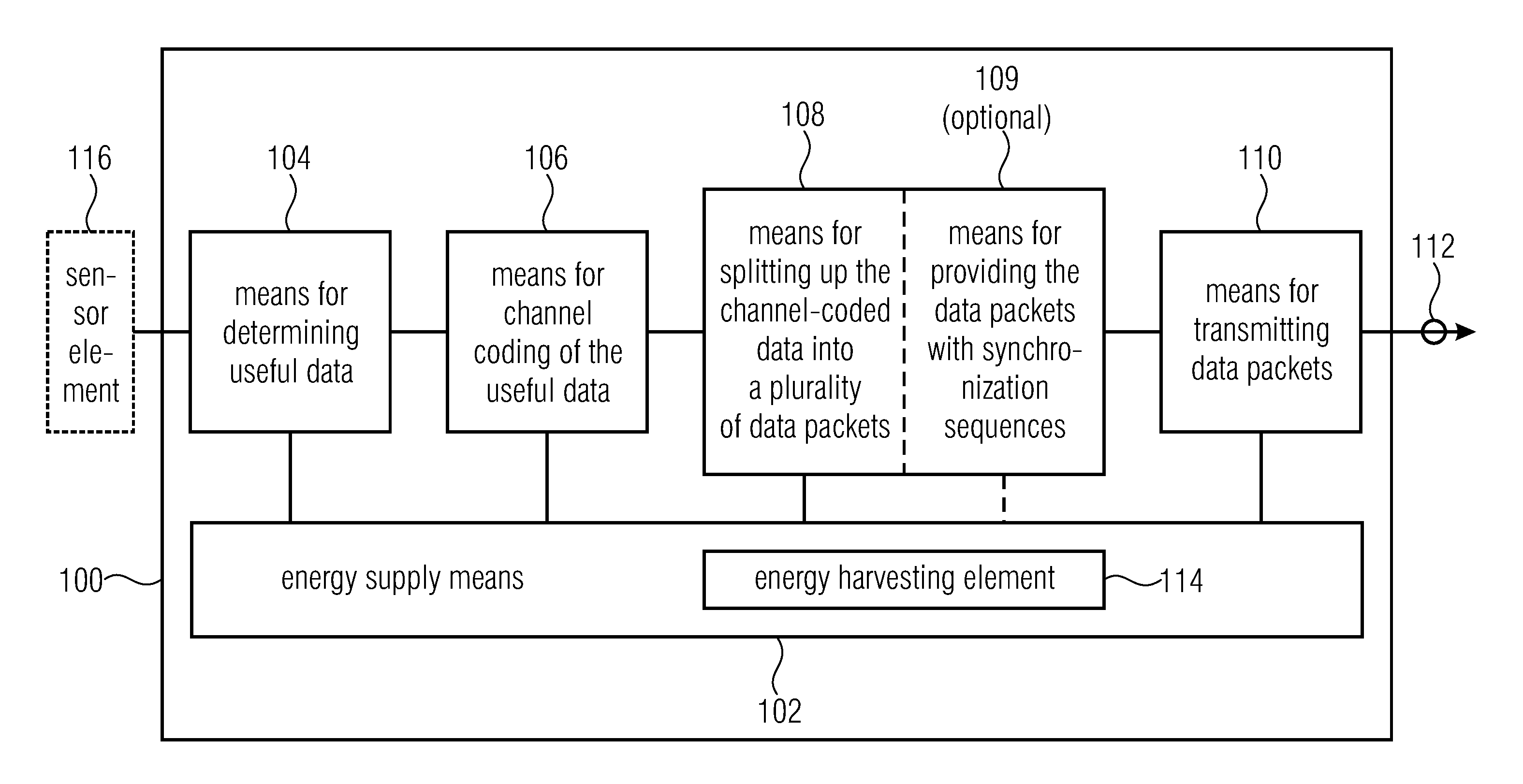
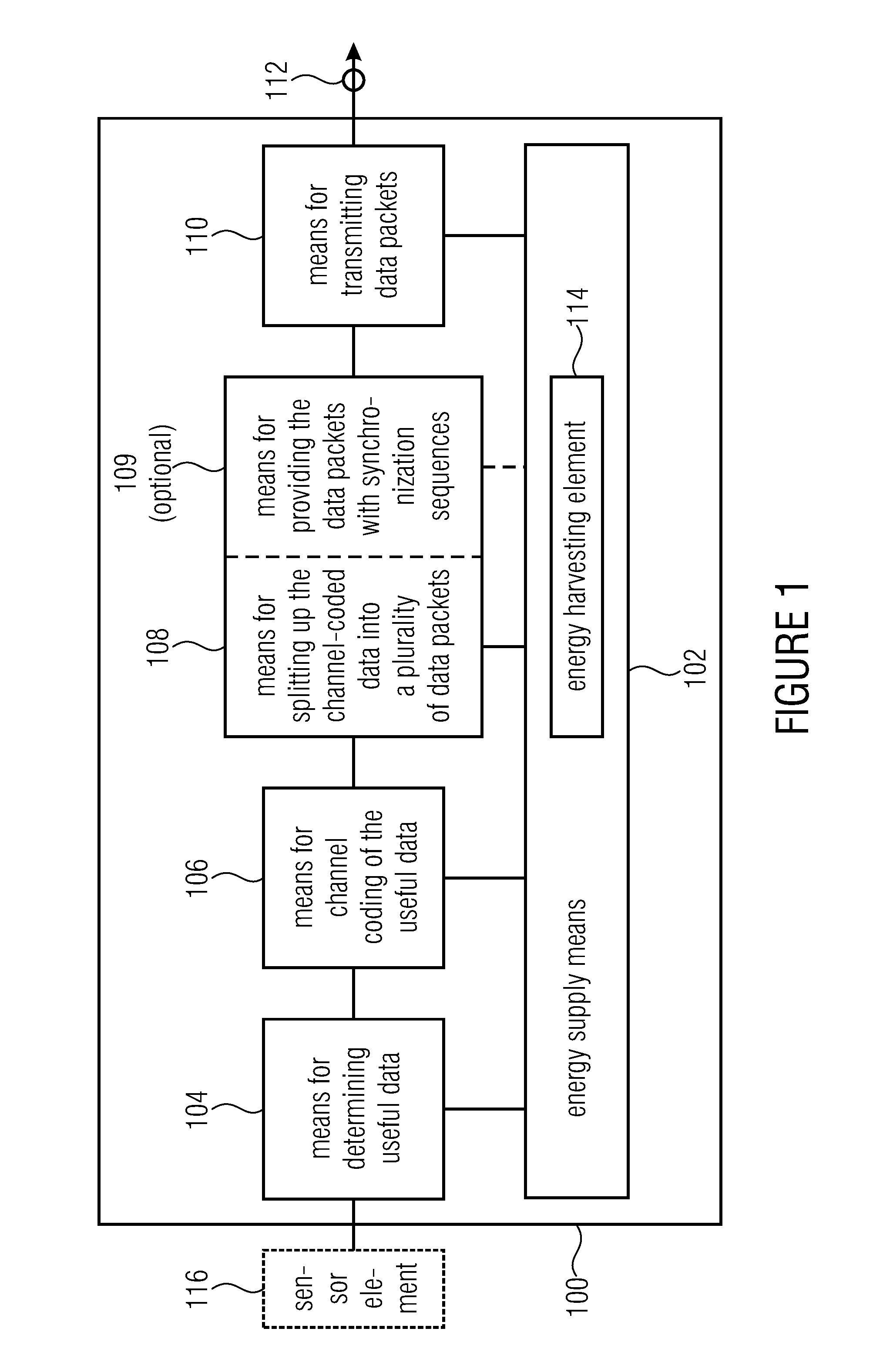
[0039]FIG. 1 shows a schematic block diagram of a data transmission arrangement 100, in accordance with an embodiment of the present invention. The data transmission arrangement 100 includes energy supply means 102 for supplying the data transmission arrangement 100 with electrical energy.

[0040]Moreover, the data transmission arrangement 100 includes means 104 for determining useful data that is provided by a sensor element 116 connected to the data transmission arrangement 100, means 106 for channel coding of the useful data so as to obtain channel-coded data, and means 108 for splitting up the channel-coded data into a plurality of data packets having a code rate smaller than one.

[0041]In addition, the dat...


PUM


Abstract

A data transmission arrangement includes an energy supplier for supplying the data transmission arrangement with electrical energy; a determiner for determining useful data provided by a sensor element connected to the data transmission arrangement; a coder for channel coding of the useful data so as to obtain channel-coded data; a splitter for splitting up the channel-coded data into a plurality of data packets having a code rate smaller than one; and a transmitter for transmitting data packets which is configured to transmit the plurality of data packets via a communication channel with a time lag, provided that an amount of electrical energy that can be provided by the energy supplier is sufficient for transmitting the respective data packets at a standard transmitting power.

Description

CROSS-REFERENCE TO RELATED APPLICATIONS[0001]This application is a continuation of copending International Application No. PCT / EP2015 / 053947, filed Feb. 25, 2015, which is incorporated herein by reference in its entirety, and additionally claims priority from European Application No. EP 14156802.2, filed Feb. 26, 2014, which is incorporated herein by reference in its entirety.[0002]Embodiments of the present invention relate to a data transmission arrangement, to a data receiver, to a system comprising a data transmission arrangement and a data receiver, as well as to methods of operating same. Further embodiments relate to a data transmission arrangement that is self-sufficient in terms of its energy supply. Some embodiments relate to a wireless transmission method for low-powered transmitters with limited energy supply.BACKGROUND OF THE INVENTION[0003]For transmitting small amounts of data from a large number of nodes, e.g. sensor data such as heat, electricity or water meters, fo...

Claims


Application Information

Patent Timeline
Patent Type & Authority Applications(United States)
IPC IPC(8): H04W52/02H04L5/00H04L29/06
CPCH04W52/0277H04L5/0051H04L69/22Y02D30/70H04W28/0221
Inventor BERNHARD, JOSEFKILIAN, GERD
Owner FRAUNHOFER GESELLSCHAFT ZUR FOERDERUNG DER ANGEWANDTEN FORSCHUNG EV
Learn More