
Systems and methods for weight determination and closed loop speed control

a technology of weight determination and closed loop, applied in the direction of process and machine control, transportation and packaging, instruments, etc., can solve the problems of affecting the operation of the vehicle, and using power limitations based on mapped speeds in certain implementations

Inactive Publication Date: 2016-12-22
RAYMOND LTD
View PDF7 Cites 9 Cited by
  • Summary
  • Abstract
  • Description
  • Claims
  • Application Information

AI Technical Summary

Benefits of technology

The patent discusses different examples of how to do something. However, people skilled in the art can modify these examples to achieve similar benefits without changing the main idea. In simple terms, the patent allows for flexibility in how to achieve the invention's benefits without breaking it.

Problems solved by technology

This weight can have a significant impact on the operation of the material handling vehicle due to the additional load placed on the material handling vehicle.
Further, when the material is being transported by a material handling vehicle capable of elevating the load, such as a fork truck, the elevation of the load, in combination with the weight, can affect the operation of the vehicle.
For example, power limitations based on mapped speeds have been used in certain implementations.
This type of power-based, mapped speed control relies on open loop speed control which is not reproducible where tight tolerances are required, due to the open loop nature of this type of control.
Further, the open loop operation results in high levels of inaccuracy, forcing the system to take a conservative approach, which can result in the material handling vehicles being operated at less than optimal speeds.
However, after market strain gauges are often not cost effective, and are prone to failures as a result of mechanical contact.
However, these types of sensors have the disadvantage of assuming that the load is of a fixed weight and / or density.
This can result in inaccurate load estimations and, therefore, improper speed control.

Method used


Image

  • Systems and methods for weight determination and closed loop speed control
  • Systems and methods for weight determination and closed loop speed control
  • Systems and methods for weight determination and closed loop speed control

Examples


Embodiment Construction

[0031]Before any embodiments of the invention are explained in detail, it is to be understood that the invention is not limited in its application to the details of construction and the arrangement of components set forth in the following description or illustrated in the following drawings. The invention is capable of other embodiments and of being practiced or of being carried out in various ways. Also, it is to be understood that the phraseology and terminology used herein is for the purpose of description and should not be regarded as limiting. The use of “including,”“comprising,” or “having” and variations thereof herein is meant to encompass the items listed thereafter and equivalents thereof as well as additional items. Unless specified or limited otherwise, the terms “mounted,”“connected,”“supported,” and “coupled” and variations thereof are used broadly and encompass both direct and indirect mountings, connections, supports, and couplings. Further, “connected” and “coupled”...


PUM


Abstract

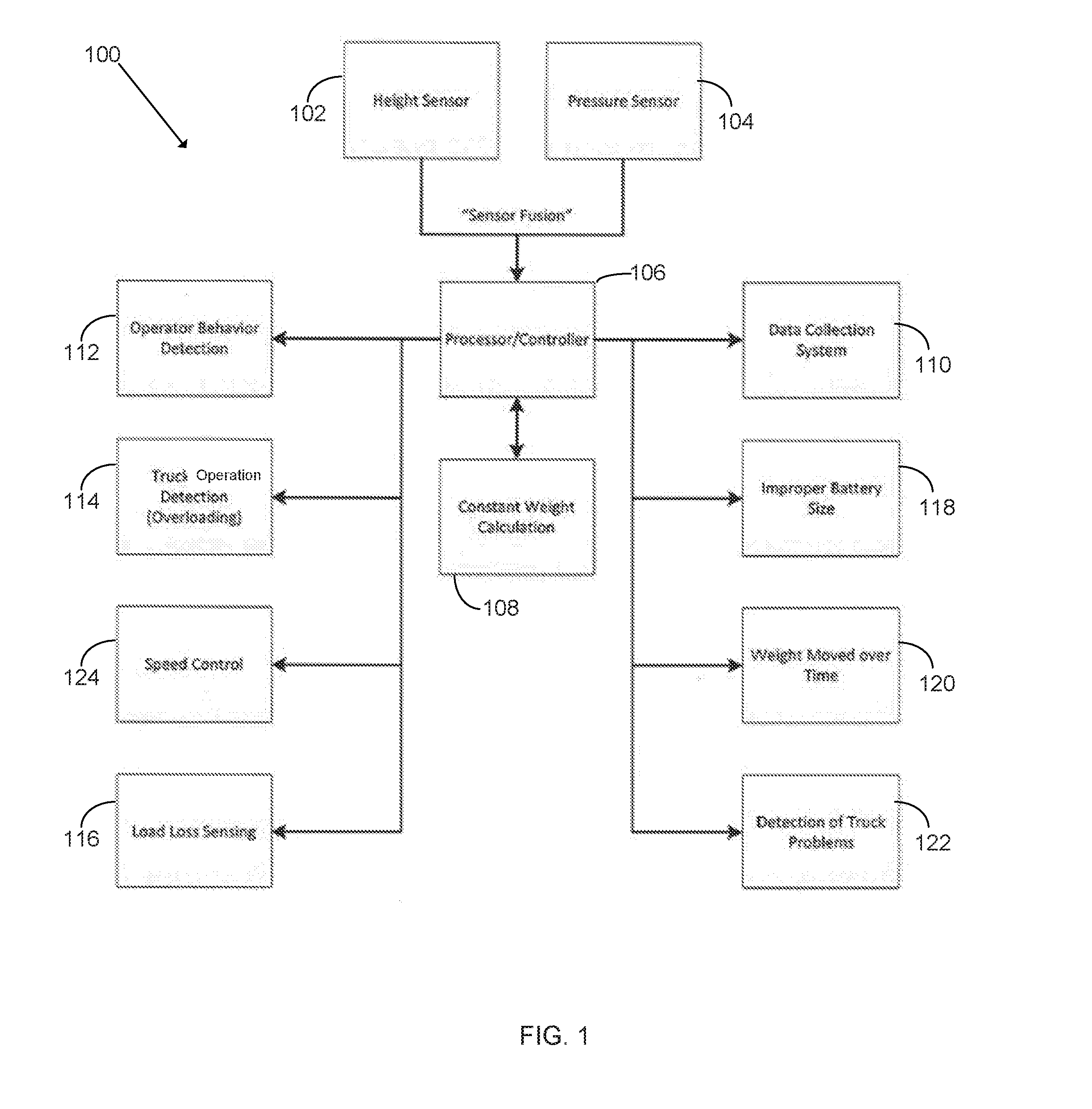
A material handling vehicle control systems and methods comprise a plurality of sensors, the plurality of sensors coupled to a material handling vehicle; a data collection system; a processor, the processor executing a real time weight calculation program, the weight calculation program comprising the steps of receiving data from the plurality of sensors; and combining the data from the plurality of sensors to continuously determine a real time weight value of a load of the material handling vehicle; the processor controlling a speed of the material handling vehicle based on at least the real time weight value.

Description

CROSS REFERENCE TO RELATED APPLICATIONS[0001]The present application is based on, claims priority to, and incorporates herein by reference in its entirety, U.S. Provisional Patent Application No. 62 / 182,338, filed Jun. 19, 2015, and entitled “Systems and Methods for Weight Determination and Closed Loop Speed Control.”STATEMENT OF FEDERALLY SPONSORED RESEARCH OR DEVELOPMENT[0002]Not applicable.FIELD OF THE INVENTION[0003]The present invention relates to material handling vehicles. More particularly, the invention relates to systems and methods for determining a load weight and to controlling the speed of a material handling vehicle using closed loop control.BACKGROUND[0004]Material handling vehicles are commonly found in warehouses, factories, shipping yards, and, generally, wherever pallets, large packages, or loads of goods are required to be transported from place to place. Material handling vehicles typically include load bearing forks for lifting packages or pallets for transpor...

Claims


Application Information

Patent Timeline
IPC IPC(8): B60W30/14G07C5/00G07C5/02B62B3/06B60W40/13
CPCB60W30/143B62B3/0612B60W40/13B60W2720/10G07C5/008B60W2300/121B60W2420/00G07C5/02B60W2530/10G05D13/66B66F9/0755B66F9/24B66F17/003B60W2556/45B60K28/16
Inventor DRISCALL, DANIEL ROBERTGREENE, ROBERT WALTER
Owner RAYMOND LTD
Learn More