Aircraft propulsion assembly with fire extinguishing system

Active Publication Date: 2016-12-22
SN DETUDE & DE CONSTR DE MOTEURS DAVIATION S N E C M A
View PDF4 Cites 7 Cited by
  • Summary
  • Abstract
  • Description
  • Claims
  • Application Information

AI Technical Summary

Benefits of technology

[0009]The present invention provides a simple, effective and eco

Problems solved by technology

However, on the ground, this ventilation is virtually non-existent and the natural convection in the annular space in the nacelle may prove to be insufficient to ensure the ventilation

Method used


Image

  • Aircraft propulsion assembly with fire extinguishing system
  • Aircraft propulsion assembly with fire extinguishing system

Examples


Example

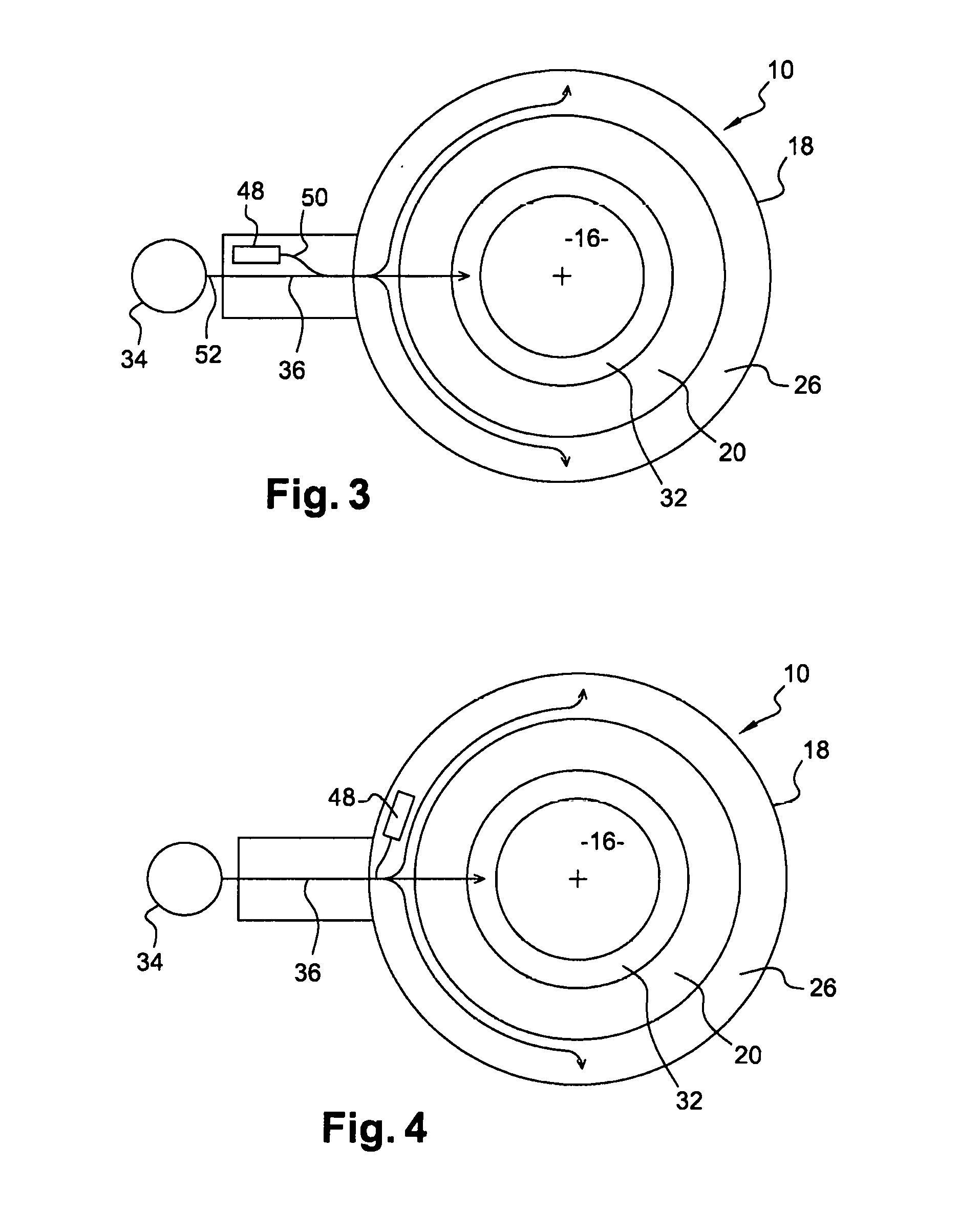
[0037]Reference is now made to FIG. 3, which shows a first embodiment of the invention.

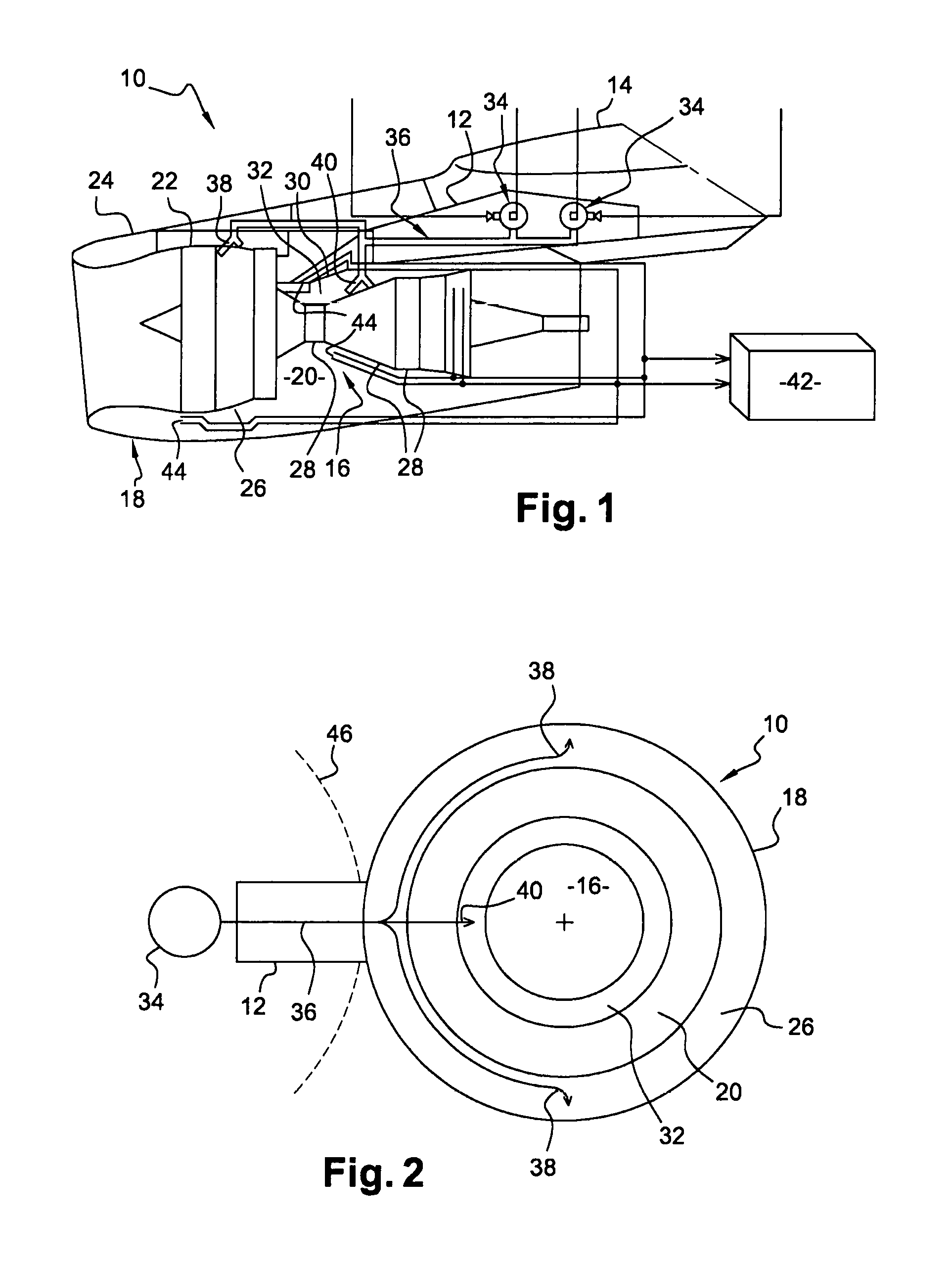
[0038]According to the invention, means are provided for supplying air to the pipe 36, this air being intended for being conveyed via the pipe 36 as far as the cavities 26, 32 in order to ventilate said cavities.

[0039]In the example shown, the air supply means comprise an electric ventilator fan 48, the air outlet 50 of which is connected to the pipe 36 in the region of the inlet 52 thereof connected to the supply means 34. This connection can be produced by means of a Y-shaped bypass (preferably upstream of the fire-resistant wall) of which one of the lateral legs is connected to the ventilator fan 48, the other lateral leg of which is connected to the supply means 34, and the central leg of which is connected to the cavities 26, 32. The connection between the ventilator fan 48 and the pipe 36 may consist of an electromagnetic valve or a non-return flap.

[0040]The ventilator fan 48 may be designed...


PUM


Abstract

An aircraft propulsion assembly includes an engine, a nacelle surrounding the engine, and a system for extinguishing a fire that may occur in the engine and/or in the nacelle. The extinguishing system has means for supplying an extinguishant to at least one extinguishant distribution pipe which opens into a cavity of the engine and/or a cavity of the nacelle. The extinguishing system also includes means for supplying said at least one pipe with air so as to ventilate the or each cavity.

Description

TECHNICAL FIELD[0001]The present invention relates to the field of ventilation of an aircraft propulsion assembly.PRIOR ART[0002]An aircraft propulsion assembly comprises an engine and a nacelle surrounding said engine, which is generally a turbine engine. The nacelle comprises a rotationally symmetrical casing which defines an annular flow duct for a flow of air around the engine, this flow of air being referred to as the secondary flow in the case of a bypass turbine engine. The nacelle defines a first annular cavity around the casing. Some equipment in the propulsion assembly is mounted in the nacelle, i.e. in the aforementioned annular cavity, and can be fastened to the casing of said nacelle. The external wall of the nacelle generally comprises removable cowls for allowing access to this equipment during a maintenance operation.[0003]The engine comprises an internal annular flow duct for a flow of air referred to as the primary flow in the case of a bypass turbine engine. The e...

Claims


Application Information

Patent Timeline
IPC IPC(8): B64D45/00F01D25/24B64C7/02
CPCB64D45/00B64C7/02F05D2220/323B64D2045/009F01D25/24B64D29/00F02C7/12F02C7/25Y02T50/60A62C3/08
Inventor CHARLEMAGNE, PIERRICKLEROUX, DELPHINE
Owner SN DETUDE & DE CONSTR DE MOTEURS DAVIATION S N E C M A
Why Eureka
Try Eureka