Locking structure, container utilizing locking structure, and container assembling apparatus

a technology of locking structure and assembling apparatus, which is applied in the direction of paper/cardboard containers, container making machinery, packaging, etc., can solve the problems of difficulty in automatic assembly and increased cost, and achieve the effect of easy locking and easy and sure locking

Active Publication Date: 2016-12-22
RENGO CO LTD
View PDF2 Cites 4 Cited by
  • Summary
  • Abstract
  • Description
  • Claims
  • Application Information

AI Technical Summary

Benefits of technology

[0014]In the locking structure of the present invention, when the second panels (side panels) are folded against the first panel (bottom panel), the locking receiving portion defined by the first and the second inclined lines and the cut portion is raised stereoscopically against the first panel and the second panels. Accordingly, by merely arranging the third panel (locking piece) along the second panel, the locking portion of the third panel can be easily locked to the locking receiving portion. In the container utilizing such a locking structure, by rotating the closure flap, the locking piece (third panel) on which an elastic restoring force acts is rotated while being brought into slide contact with an inner surface of the side panel (second panel) and hence, the locking portion can be easily and surely locked to the raised locking receiving portion. In the container assembling apparatus, positioning of the locking piece on the inner surface side of the side panel is performed by the positioning member and hence, in rotating the closure flap by the swing member, it is possible to prevent the locking piece from interfering with the end edge of the side panel. Accordingly, automatic container assembling by the apparatus can be certainly realized.

Problems solved by technology

However, in assembling the tray disclosed in patent document 1, it is necessary to hold the closure flaps and the locking pieces, and to position and insert the inserting members of the locking pieces into the insertion holes with an operator's fingers while maintaining such a state, complexing an assembling operation.
Further, it is extremely difficult to automatically assemble such a tray which requires a complex assembling operation using an apparatus, and the apparatus requires a complicated mechanism so that a cost is pushed up.

Method used


Image

  • Locking structure, container utilizing locking structure, and container assembling apparatus
  • Locking structure, container utilizing locking structure, and container assembling apparatus
  • Locking structure, container utilizing locking structure, and container assembling apparatus

Examples


first embodiment

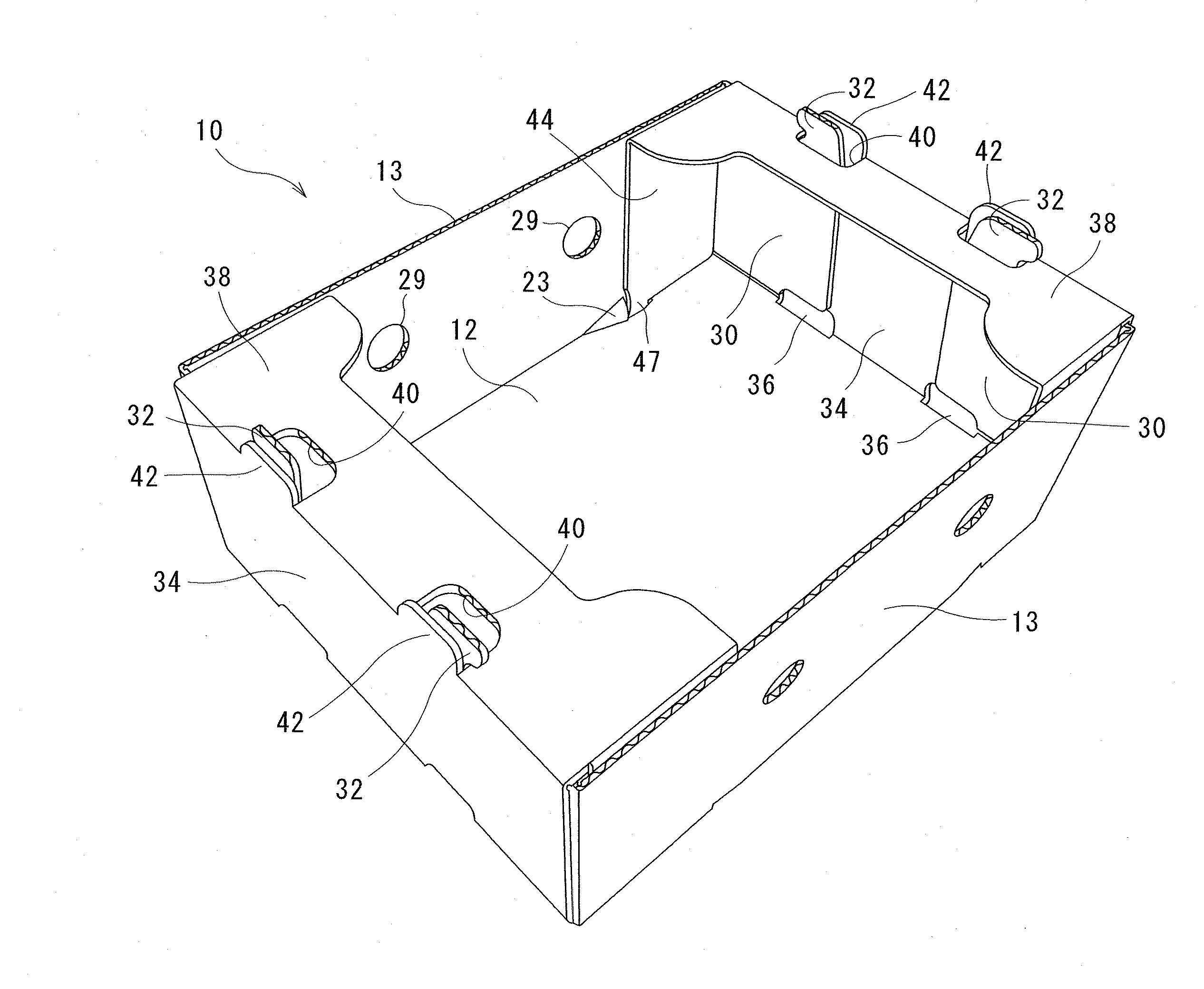
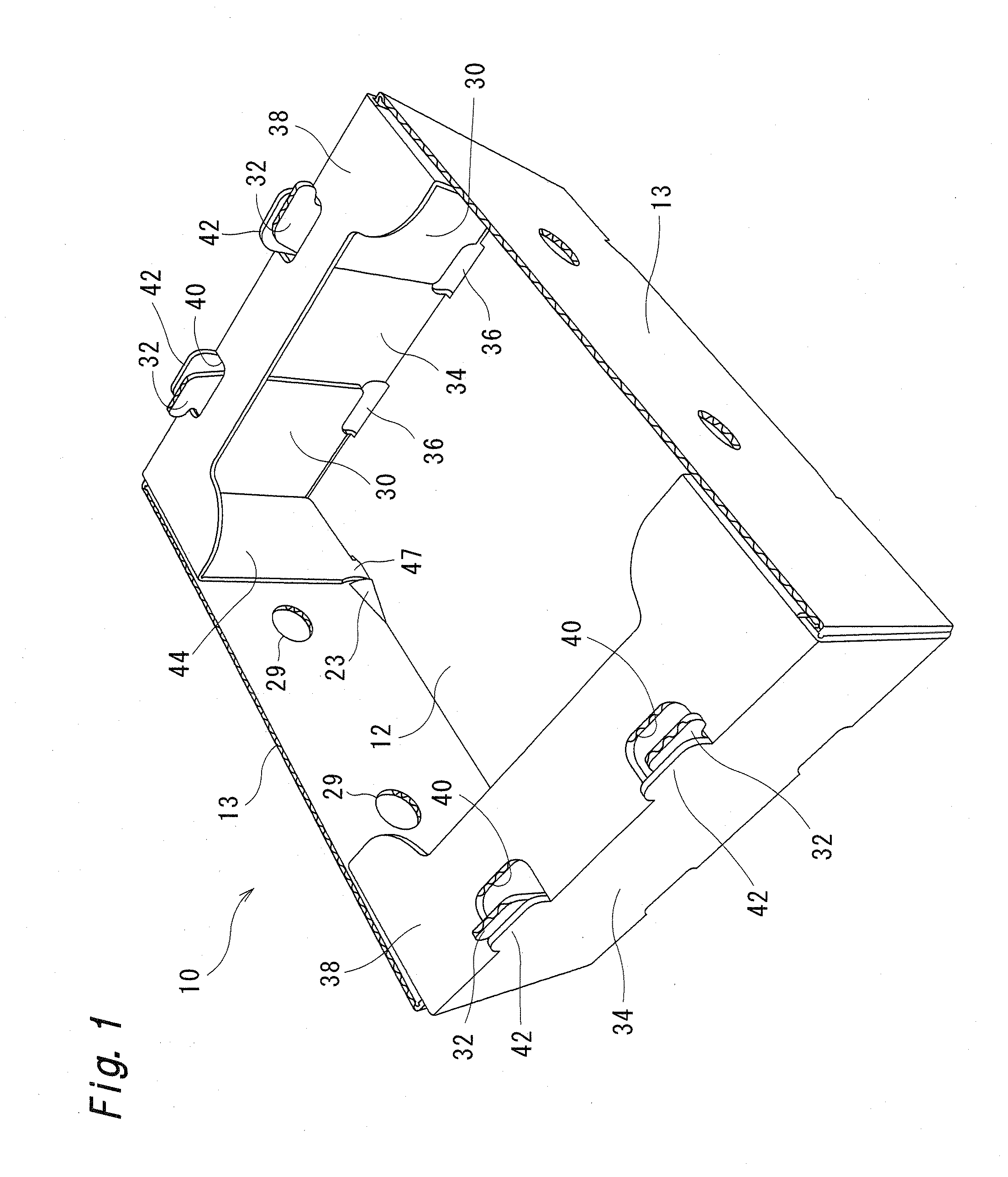
[0039]FIG. 1 shows a tray 10 of a first embodiment formed using a corrugated paper board and having a locking structure of the present invention. The tray 10 forming a container is a box which includes: a bottom panel (first panel) 12; side panels (second panels) 13; and end panels 34. An upper end of the tray 10 is opened, and portions of an upper end opening are partially covered by closure flaps 38. The corrugated paper board has a well-known structure where a corrugated-shaped intermediate core is disposed between a front liner and a back liner.

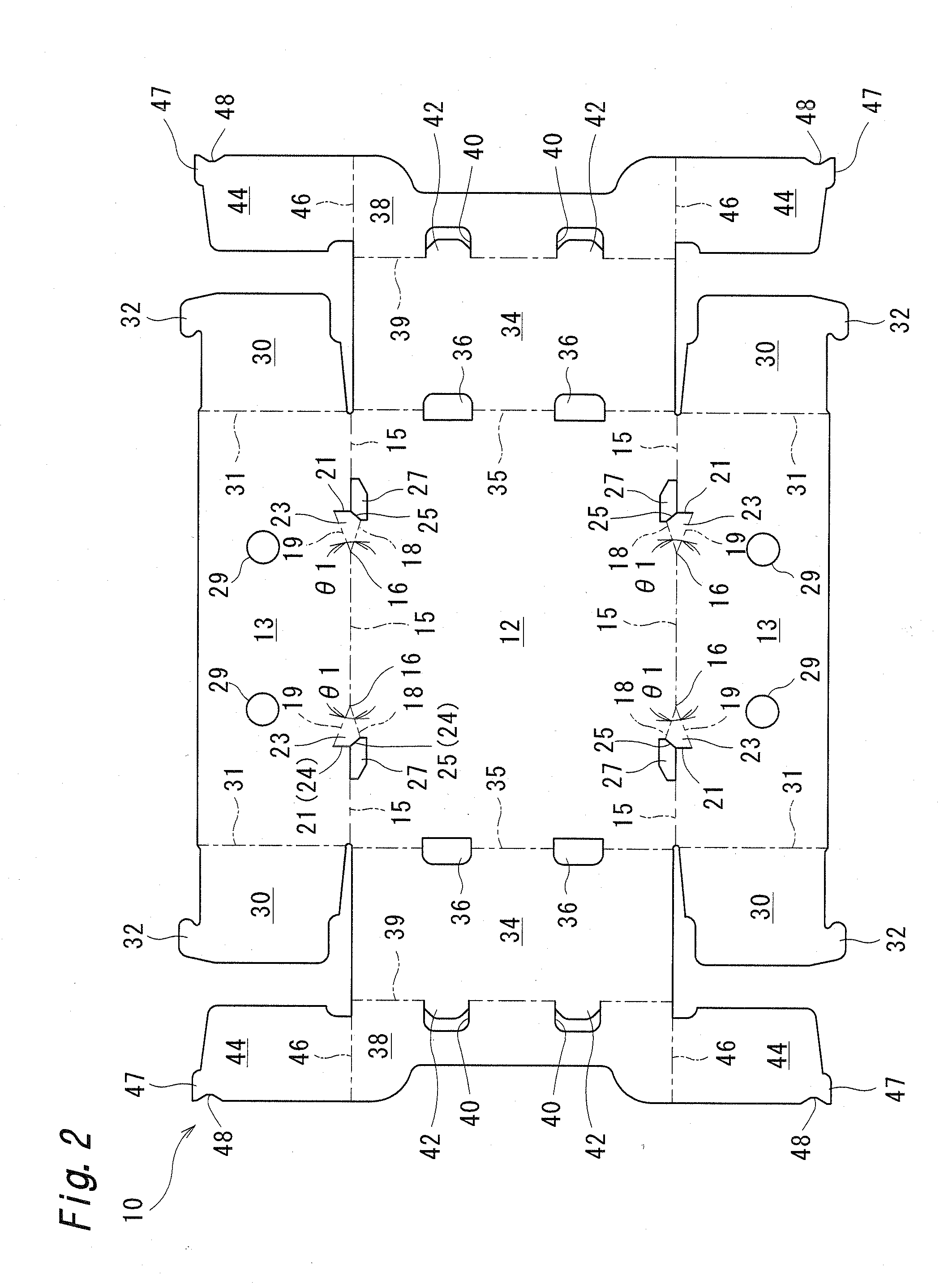
[0040]As shown in FIG. 2, a pair of side panels 13, 13 is connected to long sides (two sides opposite to each other) of the rectangular bottom panel 12, and a pair of end panels 34, 34 is connected to short sides (two sides opposite to each other) of the rectangular bottom panel 12.

[0041]The side panels 13 have a rectangular plate shape, are formed continuously with the bottom panel 12, and are folded against the bottom panel 12 at a righ...

second embodiment

[0060]FIG. 8 shows a tray 10 of a second embodiment. Elements identical to those the trays 10 of the first embodiment are given the same symbols, and the description of such elements is omitted. The tray 10 of this embodiment differs from the tray 10 of the first embodiment in that locking receiving portion 23 and cutout portions 27 are formed on each boundary portion between a side panel 13 and a folding flap 30. In the second embodiment, the folding flap 30 corresponds to the first panel, the side panel 13 corresponds to the second panel, and a locking piece 44 corresponds to the third panel. A locking recessed portion 48 is formed on an outer end edge 45 of each locking piece 44. In the second embodiment, the cutout portions 27 may not be formed.

[0061]In the second embodiment, the side panels 13 are folded against a bottom panel 12, and the folding flaps 30 are folded against the side panels 13. Due to such operations, each locking receiving portion 23 is raised so as to be incli...

third embodiment

[0062]FIG. 9 shows a tray 50 of a third embodiment. In the tray 50, side panels (second panels) 52 are connected to long sides of a bottom panel (first panel) 51, and end panels 53 are connected to short sides of the bottom panel 51. Locking receiving portions 55, cutout portions 56, and a side-panel fold line (first fold line) 54 are formed on each boundary portion between the bottom panel 51 and the side panel 52. An end-panel fold line (second fold line) 57 is formed on each boundary portion between the bottom panel 51 and the end panel 53. Rectangular locking pieces (third panels) 58 are connected to outer edges of the end panel 53. A locking-piece fold line 59 is formed on each boundary portion between the locking piece 58 and the end panel 53. A locking lug 60 projecting toward the side panel 52 is formed on an inner corner portion of each locking piece 58, and a locking recessed portion 61 is formed between the locking lug 60 and an outer end edge of the locking piece 58.

[006...


PUM


Abstract

A locking receiving portion is defined by a first inclined line extending toward a third panel side on a first panel from a branching point on a fold line between the first panel and a second panel, a second inclined line extending toward the third panel side on the second panel from the branching point, and a cut portion extending between a distal end of the first inclined line and a distal end of the second inclined line. The locking receiving portion extends in an inclined manner between the first panel and the second panel in an assembled state. A locking portion is formed on the third panel, and configured to be locked to a cut portion side of the locking receiving portion in an assembled state.

Description

TECHNICAL FIELD[0001]The present invention relates to a locking structure for maintaining a paper product in an assembled state, a tray-shaped container using the locking structure, and an apparatus for automatically assembling the container.BACKGROUND ART[0002]Patent document 1 discloses a tray made by a corrugated paper board and provided with closure flaps which cover a portion of an upper end opening of a tray body. In such a tray, fruits or vegetables are stored in the tray body in a state where the closure flaps are outwardly inclined. After the fruits or vegetables are stored, the closure flaps are folded in a horizontal direction, and inserting projections of locking pieces formed on both side edges of the closure flaps are inserted into insertion holes formed in the tray body, thus assembling the tray.[0003]However, in assembling the tray disclosed in patent document 1, it is necessary to hold the closure flaps and the locking pieces, and to position and insert the insertin...

Claims


Application Information

Patent Timeline
Patent Type & Authority Applications(United States)
IPC IPC(8): B65D5/00B31B3/50B31B50/48
CPCB65D5/0045B31B2203/105B31B2203/084B31B3/50B65D5/0025B65D5/003B65D5/2047B65D5/30B65D5/3671B31B50/81B31B2120/30B31B50/784B31B2100/0024B31B2120/502B31B50/50
Inventor MAKIUCHI, TAKAFUMIAZUMA, NORIYOSHIYAMADA, HARUHIKOOKUDA, TAKAHIROKURODA, TOKIMASANISHIKAWA, YOICHI
Owner RENGO CO LTD
Why Eureka
Try Eureka