
Self-Removing Plug for Pressure Isolation in Tubing of Well

Inactive Publication Date: 2016-12-29
WEATHERFORD TECH HLDG LLC
View PDF2 Cites 74 Cited by
  • Summary
  • Abstract
  • Description
  • Claims
  • Application Information

AI Technical Summary

Benefits of technology

The patent describes an arrangement where a temporary mandrel can be removed from a slip, cone, and seal element in response to a predetermined load. This allows the seal element to define a seating area for a plug deployed down the tubular. The patent also describes the features of the rings and the expansion ring, which can be designed in different ways to enhance sealing. The technical effect of the patent is to provide a reliable and flexible sealing solution for use in oil and gas drilling operations.

Problems solved by technology

As will be appreciated, retrieving the plugs and milling out the plugs can both take a considerable amount of time and can increase operation costs.

Method used


Image

  • Self-Removing Plug for Pressure Isolation in Tubing of Well
  • Self-Removing Plug for Pressure Isolation in Tubing of Well
  • Self-Removing Plug for Pressure Isolation in Tubing of Well

Examples


Embodiment Construction

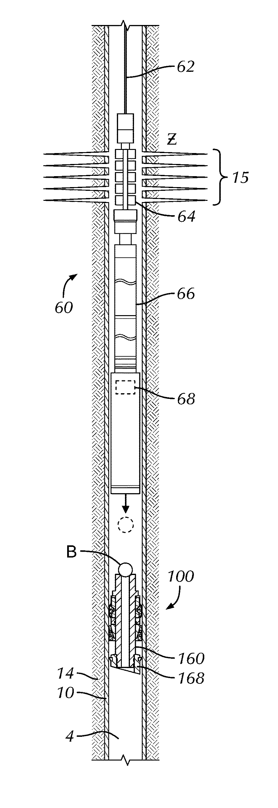
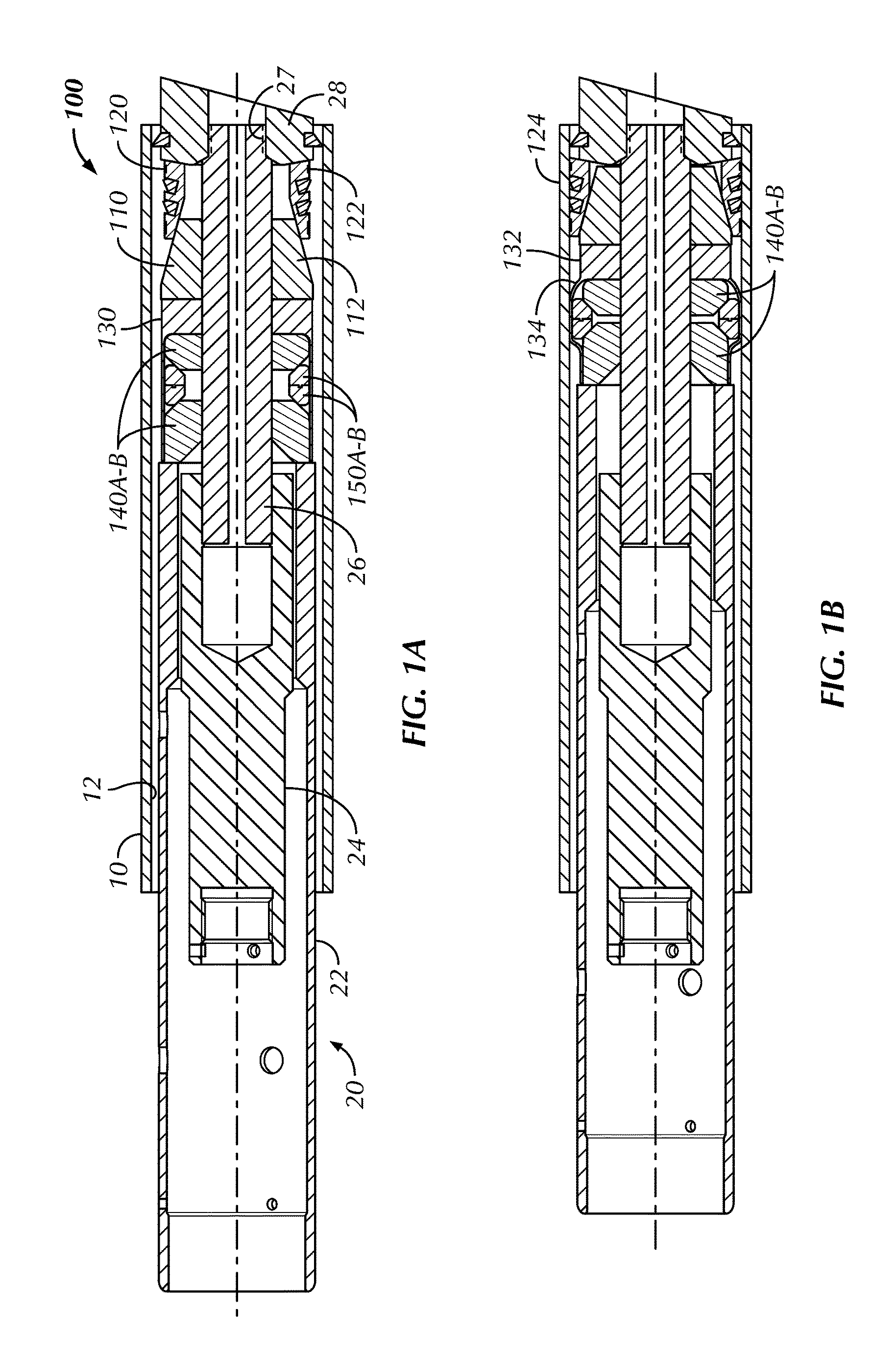
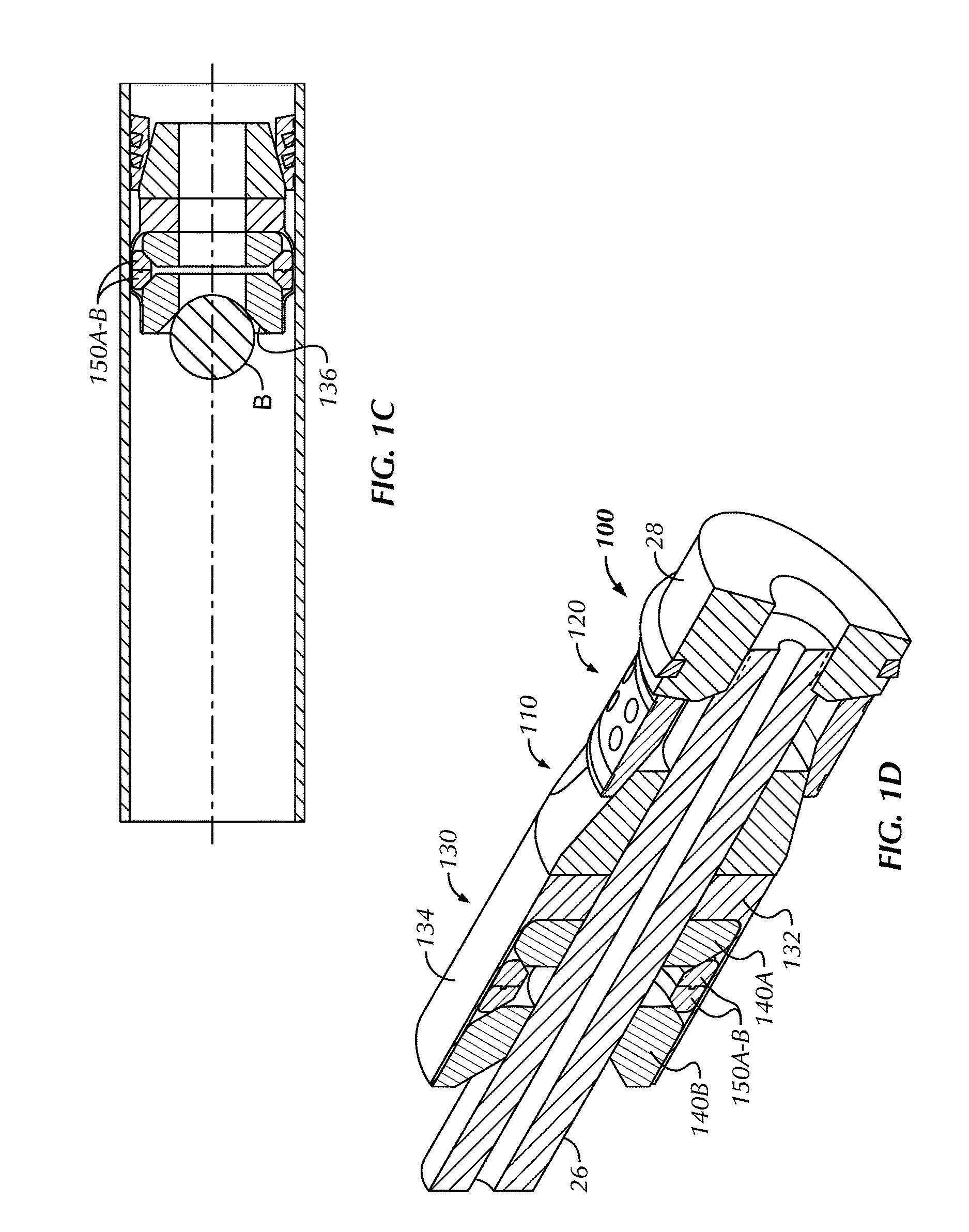
[0067]FIGS. 1A-1C illustrate cross-sectional views of a first self-removing plug 100 according to the present disclosure during stages of setting in tubing, such as cemented casing 10. FIG. 1D illustrates a perspective view of the first self-removing plug 100 in cross-section. The plug 100 includes a cone 110, a slip 120, and a seal element (having a sealing sleeve or sheath 130, body rings 140A-B, and expansion element or rings 150A-B).

[0068]This plug 100 (as well as the other plugs disclosed herein) is self-removing. For example, the various components of this plug 100 and the others disclosed herein can be composed of a dissolvable material. In one embodiment, such a dissolvable material can include a reactive metal, such as a magnesium alloy. One particular magnesium alloy is SoluMag™ available from Magnesium Elektron Alloys. Other reactive metals, such as calcium, magnesium, aluminum, can be used and can include alloying elements of calcium, magnesium, aluminum, lithium, galliu...


PUM


Abstract

A downhole apparatus for use in a tubular include a mandrel, a first slip, a cone, and a seal element. The mandrel, which can be permanent or temporary, has a first end shoulder. The first slip is disposed on the mandrel adjacent the first end shoulder, and the cone is disposed on the mandrel adjacent the first slip. The cone is movable relative to the first end shoulder to engage the first slip toward the tubular. The seal element is disposed on the mandrel adjacent the cone. At least a portion of the seal element is composed of a dissolvable metallic material and is expandable outward from the mandrel. The expanded portion of the seal element forms a metal seal against the tubular and seals off fluid communication in the annular space between the seal element and the tubular.

Description

CROSS-REFERENCE TO RELATED APPLICATIONS[0001]This application claims the benefit of U.S. Prov. Appl. No. 62 / 183,551, filed 23-Jun. 2015; 62 / 252,945, filed 9 Nov. 2015; and 62 / 303,121, filed 3 Mar. 2016, each of which is incorporated herein by reference in its entirety.BACKGROUND OF THE DISCLOSURE[0002]In wellbore construction and completion operations, a wellbore is formed to access hydrocarbon-bearing formations (e.g., crude oil and / or natural gas) by drilling a wellbore. Drilling is accomplished by utilizing a drill bit that is mounted on the end of a drill string. To drill the wellbore to a predetermined depth, the drill string is often rotated by a top drive or rotary table on a surface platform or rig, and / or by a downhole motor mounted towards the lower end of the drill string.[0003]After drilling to the predetermined depth, the drill string and drill bit are removed and a section of casing is lowered into the wellbore. An annulus is thus formed between the string of casing an...

Claims


Application Information

Patent Timeline
IPC IPC(8): E21B33/12E21B33/134E21B43/116E21B43/14E21B23/06E21B29/02E21B33/128E21B43/26
CPCE21B33/1212E21B33/128E21B33/134E21B43/261E21B2034/002E21B23/06E21B29/02E21B43/116E21B43/14E21B33/129E21B34/063E21B34/06E21B2200/04
Inventor ROCHEN, JAMES A.MHASKAR, NAUMAN H.SETTERBERG, JR., JOHN R.CRUMP, MATTHEW A.
Owner WEATHERFORD TECH HLDG LLC
Features
  • Generate Ideas
  • Intellectual Property
  • Life Sciences
  • Materials
  • Tech Scout
  • Unparalleled Data Quality
  • Higher Quality Content
  • 60% Fewer Hallucinations
Learn More