Runaway valve system for a pump

Active Publication Date: 2016-12-29
CARLISLE FLUID TECH INC
View PDF5 Cites 9 Cited by
  • Summary
  • Abstract
  • Description
  • Claims
  • Application Information

AI Technical Summary

Benefits of technology

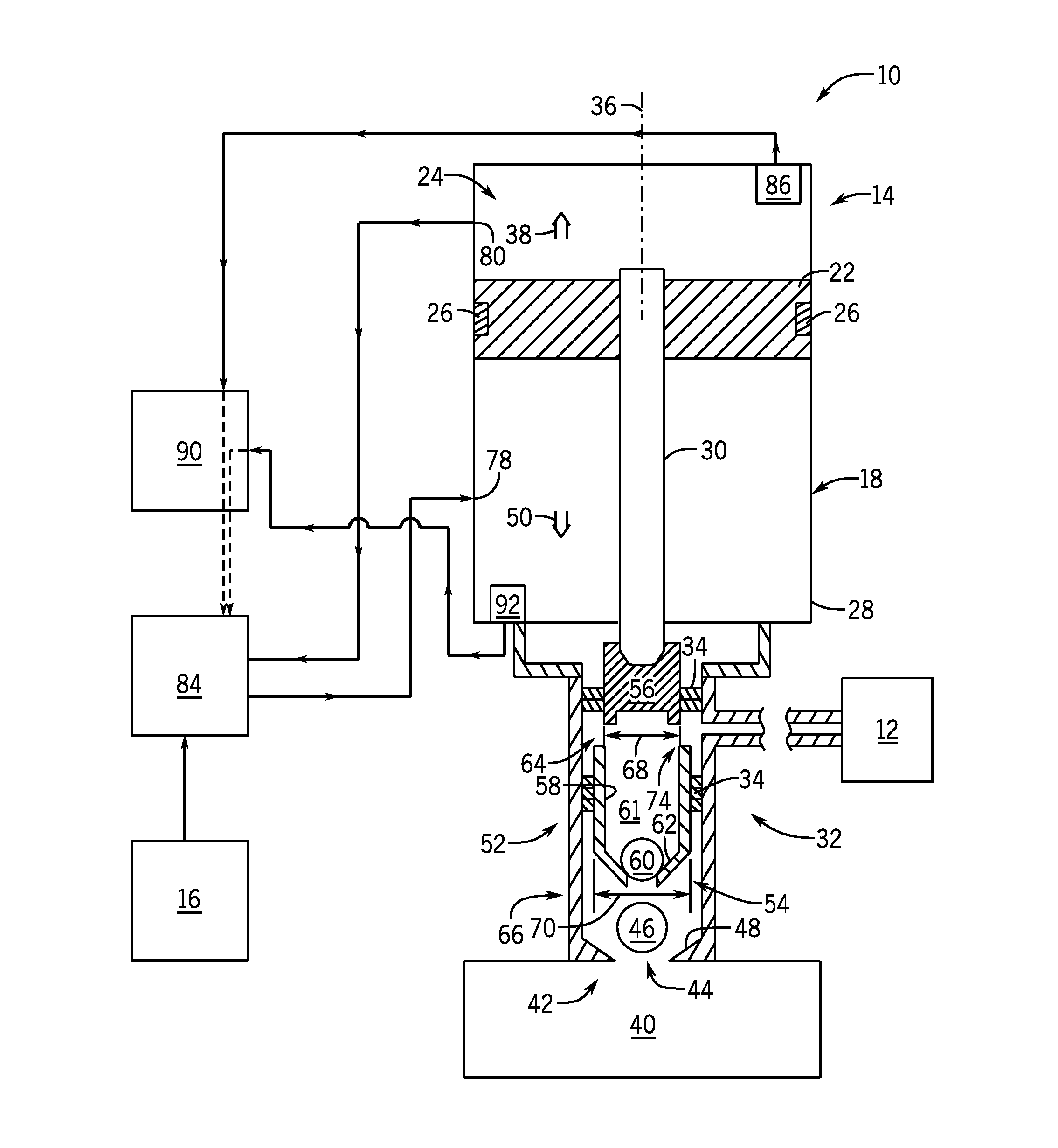
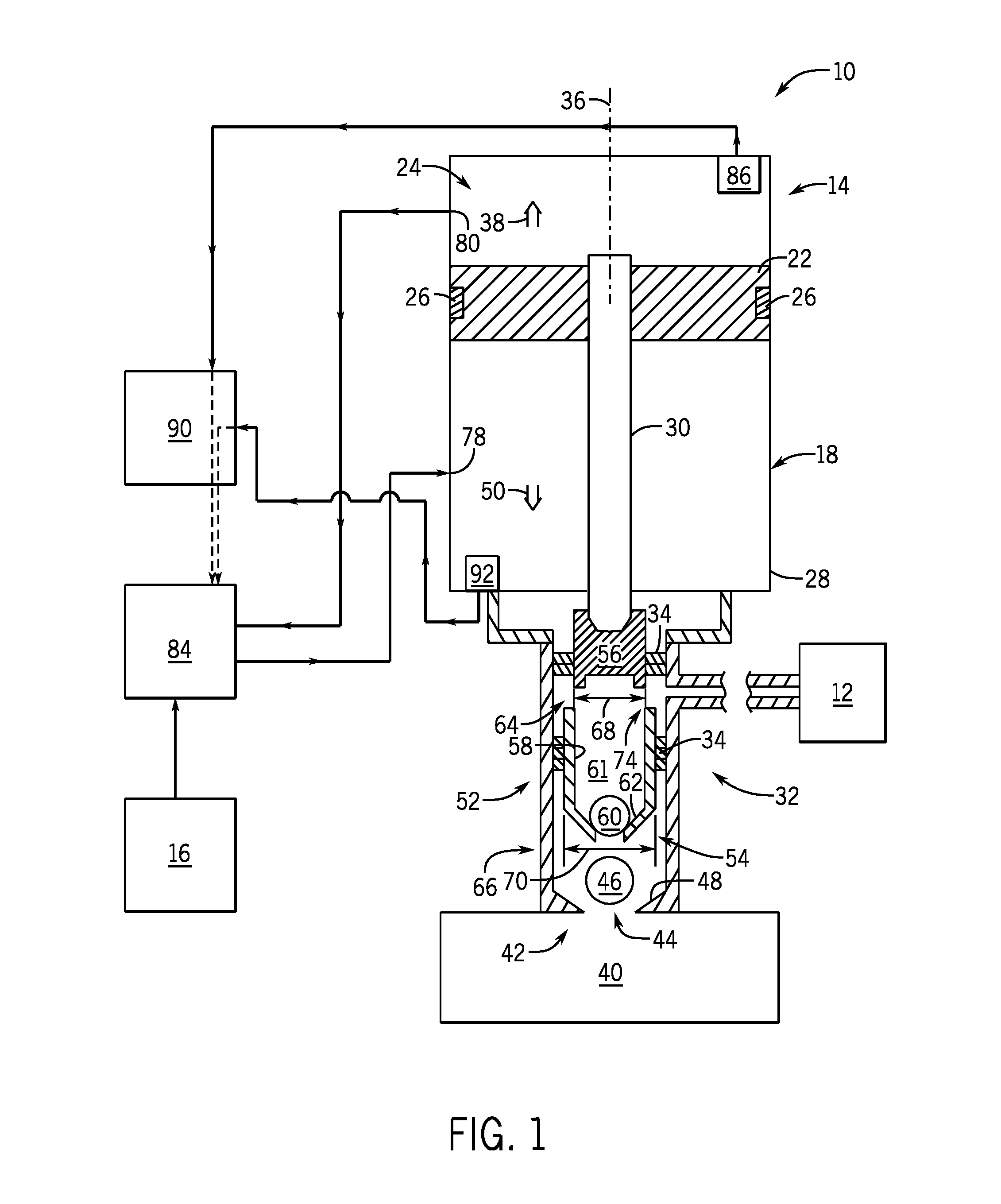
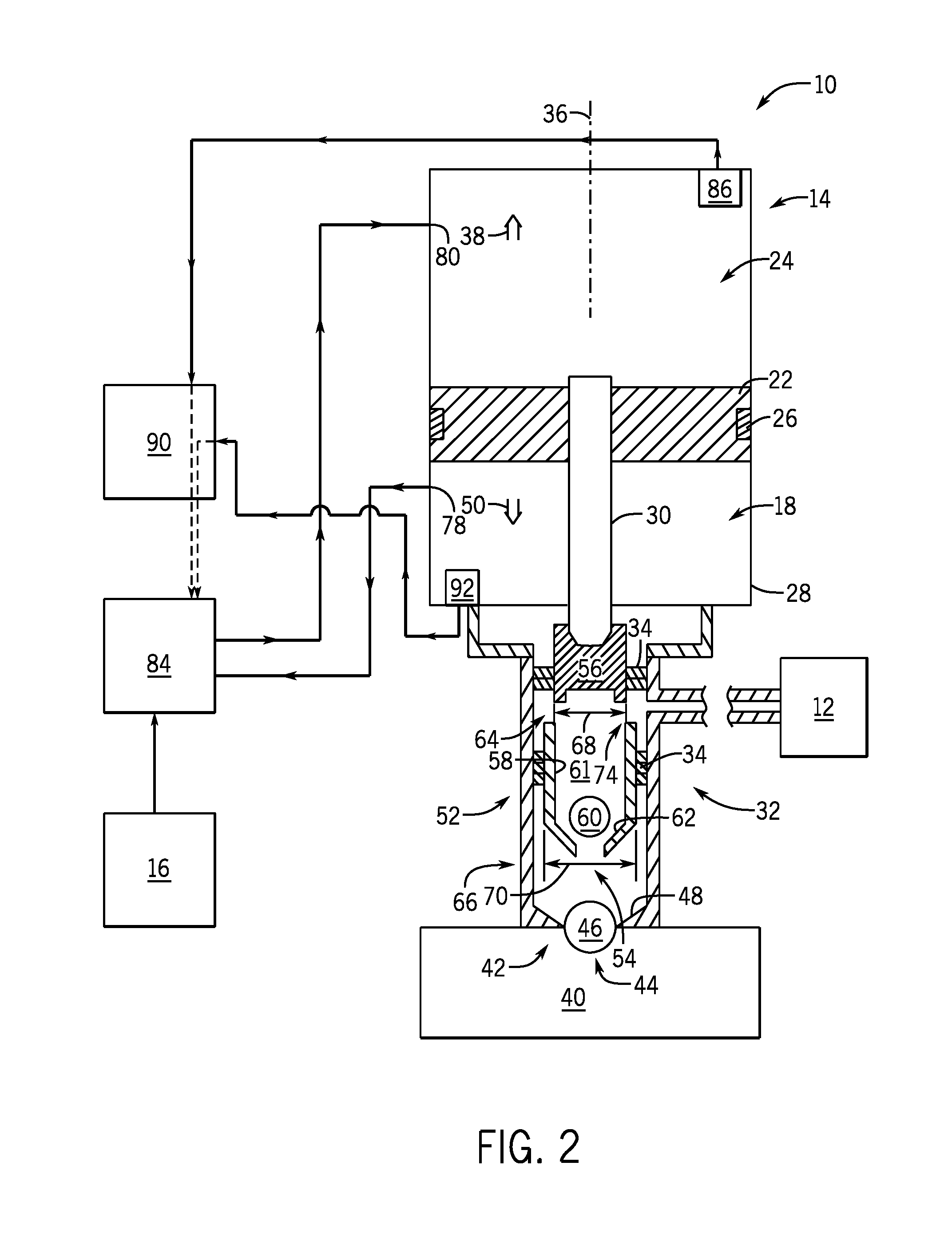
[0005]A system includes a pump. The pump includes a piston configured to axially reciprocate within a body. The axial movement of the piston activates a first chamber valve and a second chamber valve. The system also includes a main valve configured to direct a flow to the pump to facilitate the axial movement which then transfers a fluid from a reservoir to a spray applicator. The system includes a runaway valve system fluidly coupled to the main valve and configured to detect a runaway state of the pump. The runaway valve s

Problems solved by technology

Unfortunately, the pump and reservoir may be positioned away from an operator using the spray gun, therefore monitoring of the level of coating material in the reservoir may be difficult.
Operati

Method used


Image

  • Runaway valve system for a pump
  • Runaway valve system for a pump
  • Runaway valve system for a pump

Examples


Embodiment Construction

[0017]One or more specific embodiments of the present disclosure will be described below. In an effort to provide a concise description of these embodiments, all features of an actual implementation may not be described in the specification. It should be appreciated that in the development of any such actual implementation, as in any engineering or design project, numerous implementation-specific decisions must be made to achieve the developers' specific goals, such as compliance with system-related and business-related constraints, which may vary from one implementation to another. Moreover, it should be appreciated that such a development effort might be complex and time consuming, but would nevertheless be a routine undertaking of design, fabrication, and manufacture for those of ordinary skill having the benefit of this disclosure. Furthermore, top, bottom, upward, downward, upper, lower, or the like may be construed as relative terms that relate, in context, to the orientation,...


PUM


Abstract

A system includes a pump. The pump includes a piston configured to axially reciprocate within a body. The axial movement of the piston activates a first chamber valve and a second chamber valve. The system also includes a main valve configured to direct a flow to the pump to facilitate the axial movement which then transfers a fluid from a reservoir to a spray applicator. The system includes a runaway valve system fluidly coupled to the main valve and configured to detect a runaway state of the pump. The runaway valve system is configured to direct the main valve to stop operation of the pump in response to detection of the runaway state.

Description

CROSS REFERENCE TO RELATED APPLICATION[0001]This application claims priority to and benefit of U.S. Provisional Patent Application No. 62 / 186,220, entitled “Runaway Valve System for a Pump”, filed Jun. 29, 2015, which is herein incorporated by reference in its entirety.BACKGROUND[0002]The present disclosure relates generally to sprayers, and more particularly, to a runaway valve system for a pneumatic pump supplying fluid to a sprayer.[0003]Sprayers, such as spray guns, may be used to apply a coating material to a wide variety of target objects. Certain spray guns use a pneumatic pump to drive the coating material from a reservoir toward a spray nozzle tip. Unfortunately, the pump and reservoir may be positioned away from an operator using the spray gun, therefore monitoring of the level of coating material in the reservoir may be difficult. Operation of the pump without coating material may lead to a runaway pump condition, where the pump does not pump coating material but rapidly ...

Claims


Application Information

Patent Timeline
IPC IPC(8): F04B49/03F04B49/06F04B23/02F04B53/10F04B53/14F04B19/22F04B9/125F04B49/22
CPCF04B49/03F04B9/125F04B49/065F04B49/225F04B2203/09F04B53/143F04B19/22F04B23/028F04B2203/10F04B53/1002B05B9/0409B05B12/08F04B49/02F04B49/10F04B2201/0201F04B49/103F15B2211/8755
Inventor STRONG, CHRISTOPHER LEE
Owner CARLISLE FLUID TECH INC
Why Eureka
Try Eureka