Vehicle Light Emitting Display Device and Vehicle Display System

Active Publication Date: 2016-12-29
YAZAKI CORP
View PDF5 Cites 19 Cited by
  • Summary
  • Abstract
  • Description
  • Claims
  • Application Information

AI Technical Summary

Benefits of technology

The patent describes a vehicle display system that can be easily installed and adjusted to provide clear visibility for the driver. This system is cost-effective and easy to operate.

Problems solved by technology

A displayer of the system disclosed in Patent Literature 1 is not capable of displaying various information items, but is capable of calling a driver's attention to any warning.
In contrast, unless the number of light emitting elements disposed on the dashboard is increased, the number of display positions of warnings is limited.
Accordingly, there is a possibility of not being able to obtain a satisfactory display capability due to large errors in display positions in a situation where the display positions of warnings are very meaningful.
If the number of light emitting elements is increased, the number of components is increased, and the cost increases.
It may be difficult to ensure a space for disposing many light emitting elements in a vehicle, or man-hours required to perform the mounting of components may increase, which is a problem.
Since the HUD device is required to project display light to the entire area of a somewhat large size, unless a high-output light source is used, it is not possible to sufficiently ensure display brightness.
A use of a high-output light source increases power consumption or the amount of generated heat, which is a problem.
In a case where display brightness is low, a driver may be highly likely to overlook a warning display.
In a case where the size of a display area of the HUD device is small, the HUD device is not capable of displaying warnings at various locations, and the freedom of controlling display positions is reduced.

Method used


Image

  • Vehicle Light Emitting Display Device and Vehicle Display System
  • Vehicle Light Emitting Display Device and Vehicle Display System
  • Vehicle Light Emitting Display Device and Vehicle Display System

Examples


first embodiment

Outline of State of Disposition and Configuration of Device

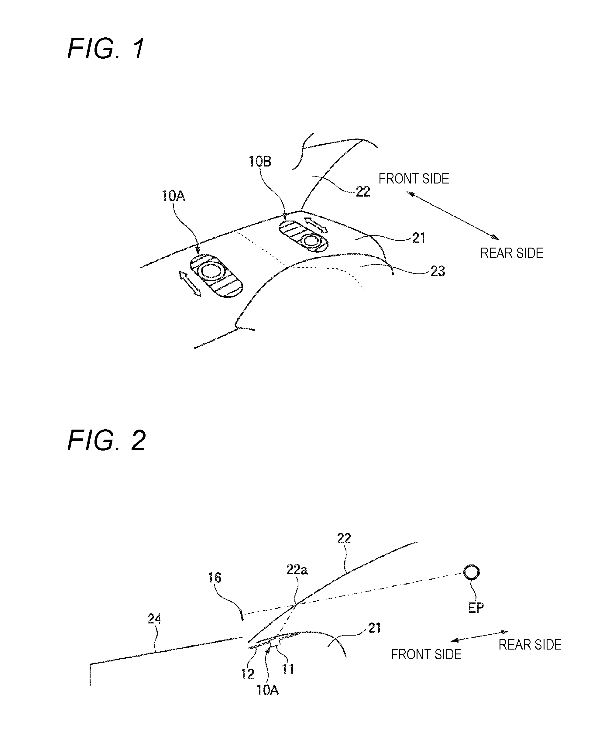
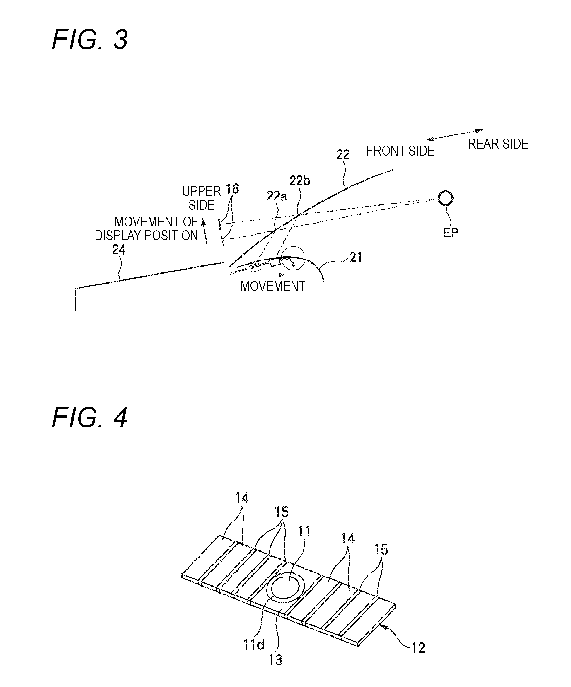
[0063]FIG. 1 illustrates a state in which a location in front of a driver's seat is viewed diagonally from the top in a passenger compartment of a vehicle equipped with vehicle light emitting display devices 10A and 10B. FIGS. 2 and 3 are sectional views illustrating the layout of portions in which the vehicle equipped with the vehicle light emitting display devices 10A and 10B is viewed from the side.

[0064]As illustrated in FIG. 1, in this example, two sets of vehicle light emitting display devices 10A and 10B are installed in a state where a portion of each of the vehicle light emitting display devices 10A and 10B is exposed on the top of an instrument panel 21 in front of a meter hood 23. One vehicle light emitting display device 10A is disposed on the left side of a central portion of the meter hood 23. The other vehicle light emitting display device 10B is disposed on the right side of the central portion of the meter h...

second embodiment

Configuration of Mechanism Unit

[0102]FIG. 11 illustrates a configuration example of an attention-calling displayer 11A included in a vehicle light emitting display device. Instead of the attention-calling displayer 11 illustrated in FIGS. 2 and 4, the attention-calling displayer 11A can be mounted and used in the belt-shaped support member 12.

[0103]As illustrated in FIG. 11, the attention-calling displayer 11A includes a center light 11a; a plurality of light rings 11b; a magnifying mirror 11c; a bezel 11d; a transparent cover 11e; and a heat sink 11f.

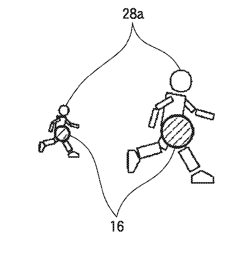
[0104]The center light 11a is equivalent to the light source 45 illustrated in FIG. 9, and emits light required to display the attention-calling display 16. A high-output light source is used as the center light 11a so as to obtain a high attention-calling effect, and thus, generates a relatively large amount of heat. The heat sink 11f is disposed in the vicinity of the center light 11a so as to reduce an increase in temperature cause...

third embodiment

Configuration and Exterior of Mechanism Unit

[0119]FIG. 15 illustrates a specific example of an exterior of a vehicle display system 100 including the vehicle light emitting display device. FIG. 16 illustrates a configuration example of the vicinity of an instrument panel of a vehicle equipped with the vehicle display system 100.

[0120]The vehicle display system 100 illustrated in FIG. 15 includes a HUD unit 51 disposed in a central portion, and attention-calling displayers 11R and 11L which are respectively disposed on right and left sides of the HUD unit 51. Similar to a typical vehicle head-up display (HUD) device, the HUD unit 51 has the function of displaying images of various text information items or various symbols, which aid the driving of the vehicle, as virtual images ahead of a visual field of the driver by projecting the images on the front windshield 22 or the like. That is, the HUD unit 51 is different from the vehicle light emitting display devices 10A and 10B in that ...


PUM


Abstract

A vehicle light emitting display device is provided with at least one light source which can be controlled to turn on and off and a light reflecting member disposed in front of a driver of a vehicle. The vehicle light emitting display device forms a virtual image which can be observed by the driver, by emitting light of the light source from lower side of an instrument panel of the vehicle toward the light reflecting member. The vehicle light emitting display device is further provided with a forward and rearward movable mechanism that freely moves a position, at which light is emitted from the light source toward the light reflecting member, in a forward and rearward direction which is a travel direction of the vehicle.

Description

CROSS REFERENCE TO RELATED APPLICATIONS[0001]This application is a continuation of PCT application No. PCT / JP2015 / 057064, which was filed on Mar. 10, 2015 based on Japanese Patent Application (No. 2014-046398) filed on Mar. 10, 2014, the contents of which are incorporated herein by reference.BACKGROUND OF THE INVENTION[0002]Field of the Invention[0003]The present invention relates to a vehicle light emitting display device and a vehicle display system which displays information by using reflection of light by a front windshield (window glass) or the like in front of a driver in a vehicle.[0004]Description of Related Art[0005]A typical vehicle head-up display (HUD) device projects beams of display light, which contain various information items to be displayed, to a front windshield or a reflective plate called a combiner via a HUD unit, and forms an optical path such that light reflected by the front windshield or the like is directed toward an eye point of a driver. Accordingly, the...

Claims


Application Information

Patent Timeline
IPC IPC(8): G08G1/16B60Q9/00B60K35/00G02B27/01
CPCG08G1/166G02B27/0101B60Q9/008B60K35/00B60K2350/2034B60K2350/2052G02B2027/0141B60K2350/1056G02B2027/014B60R21/00B60R2300/205B60R2300/308G09G3/3406G09G2320/062G09G2380/10G09G3/001G09G5/38G09G2360/04G09G2354/00G09G3/03B60K35/20B60K35/285B60K2360/331B60K2360/334B60K35/60B60K2360/785G02B27/01
Inventor AOKI, KUNIMITSU
Owner YAZAKI CORP
Why Eureka
Try Eureka