
Vehicle body front section structure

Active Publication Date: 2017-01-05
NISSAN MOTOR CO LTD
View PDF0 Cites 9 Cited by
  • Summary
  • Abstract
  • Description
  • Claims
  • Application Information

AI Technical Summary

Benefits of technology

The patent text is discussing a structure used in vehicles that can cause deformation and increase noise levels. The technical effect of the patent is to provide a new structure that can prevent this deformation and improve the sound vibration performance of the vehicle.

Problems solved by technology

As a result, a mode in which a front floor vertically vibrates is excited by the crushing deformation, change in volume of air in the vehicle interior occurs, and a problem arises that the noise level in the vehicle interior increases.
In the structure of Patent Literature 1, a space between a side surface of the floor tunnel and the floor cross member is small, and a cross section sufficient to suppress the crushing deformation is not sufficiently secured.
Therefore, the side surface of the floor tunnel to suppress the crushing deformation does not have sufficient rigidity, and additionally, a frame structure of the floor cross member cannot disperse a force acting on a floor tunnel member at the time of the crushing deformation.
As a result, the structure of Patent Literature 1 causes vehicle body deformation to thereby increase the noise level in the vehicle interior.

Method used


Image

  • Vehicle body front section structure
  • Vehicle body front section structure
  • Vehicle body front section structure

Examples


Embodiment Construction

[0021]Hereinafter, embodiments of the present invention will be explained in detail with reference to drawings. In embodiments of the invention, numerous specific details are set forth in order to provide a more thorough understanding of the invention. However, it will be apparent to one of ordinary skill in the art that the invention may be practiced without these specific details. In other instances, well-known features have not been described in detail to avoid obscuring the invention.

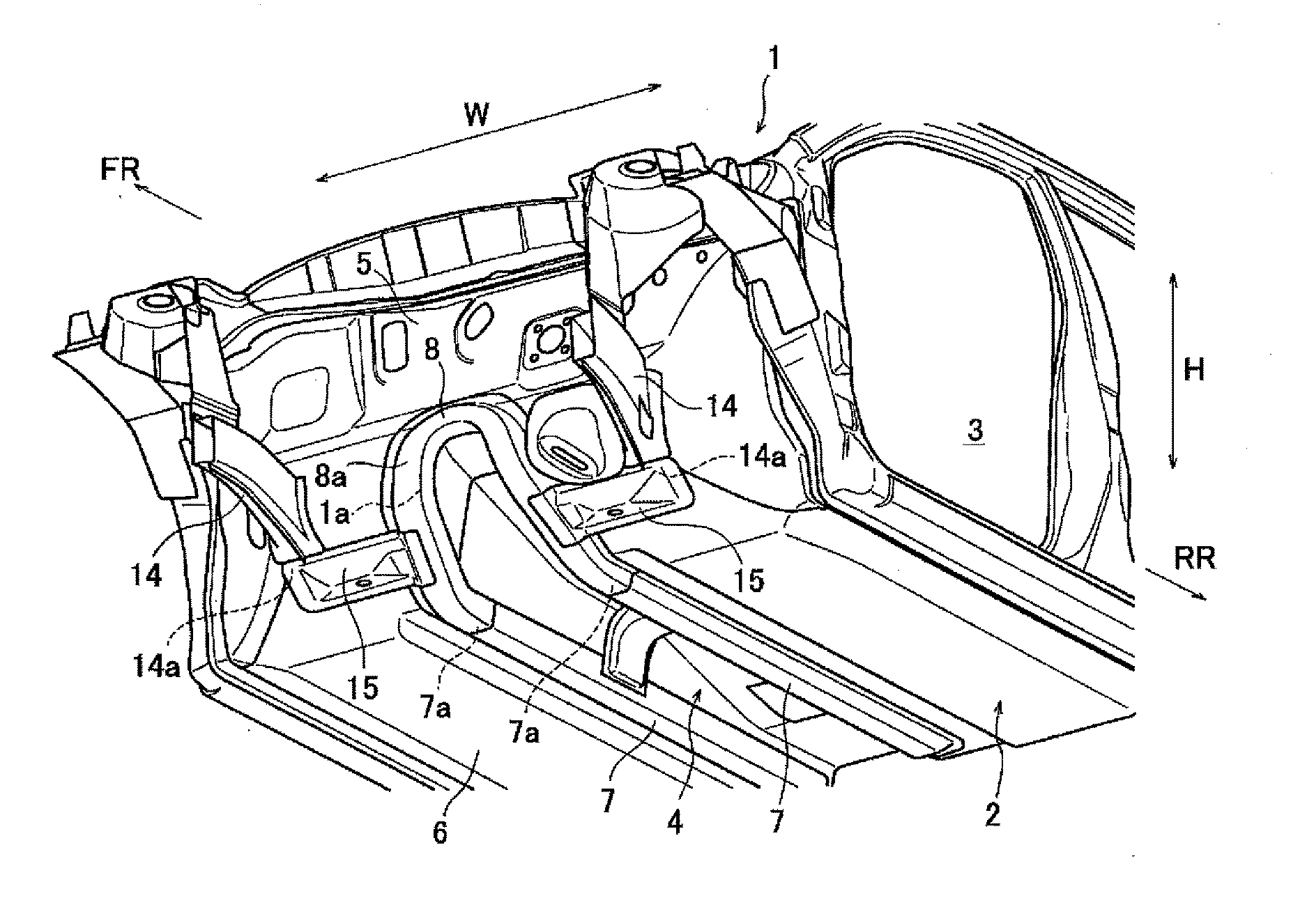
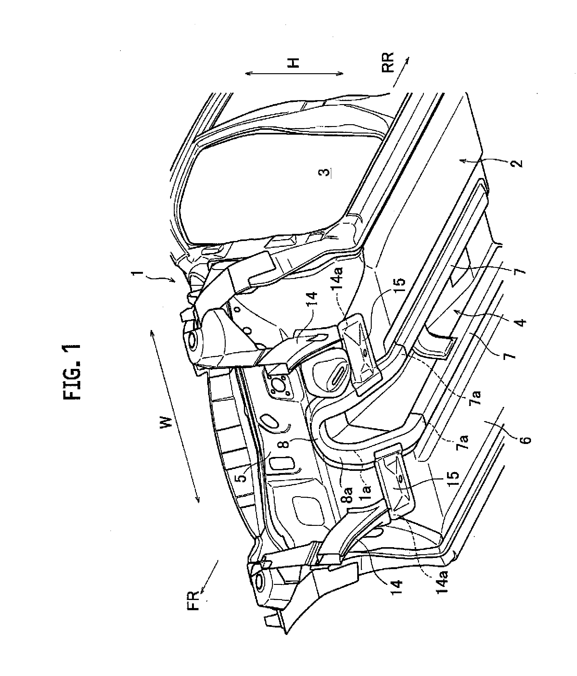
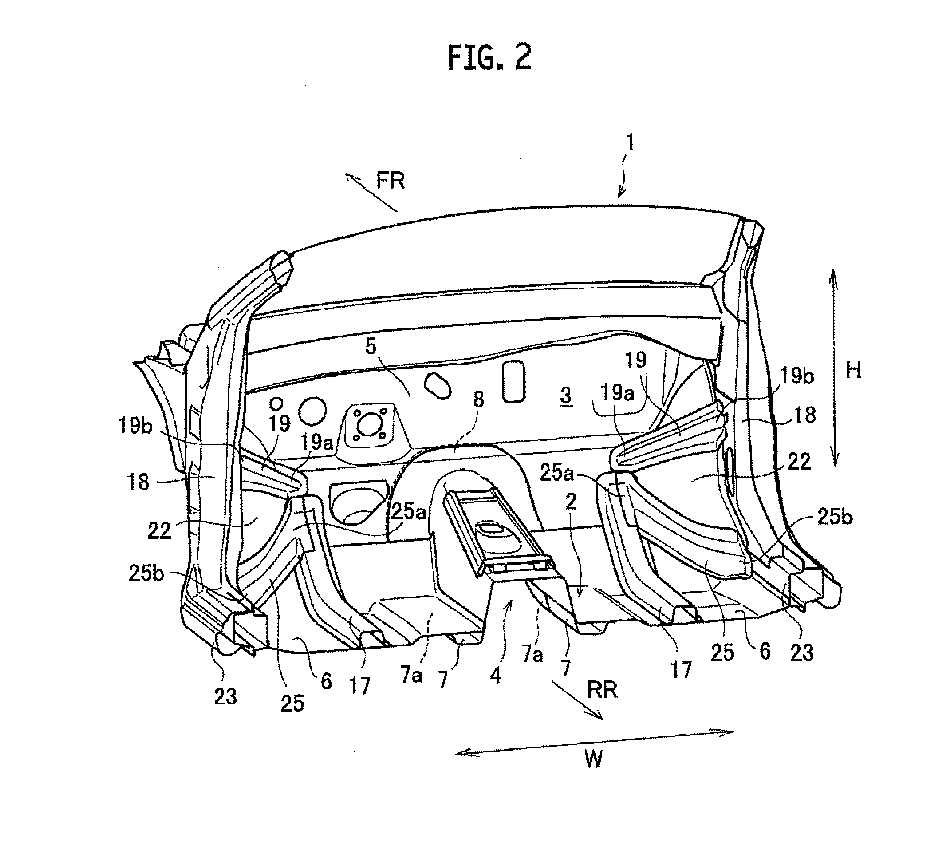
[0022]FIG. 1 is a perspective view showing structures of a front section and a lower section seen from an outside of a vehicle in a vehicle body front section structure seen from the outside of the vehicle (a perspective view in a case of looking up at a vehicle lower section from a position of a vehicle front lower part). FIG. 2 is a perspective view showing a structure in a vehicle interior of the vehicle body front section structure (a perspective view in a case of looking into an inside of the v...


PUM


Abstract

A vehicle body front section structure has a floor tunnel that projects into a vehicle interior on an underfloor of a vehicle, that is formed in a vehicle longitudinal direction, and that has a floor tunnel front end part disposed at a vehicle front of the floor tunnel, and floor tunnel members, a front end ridge line part, a first vehicle body front section reinforcing member that covers, from an outside of the vehicle, a whole of the floor tunnel front end part, from a vehicle upper end to a root of each of the floor tunnel members, and that is provided in the vehicle longitudinal direction along the front end ridge line part, and front side members, each of which has a lower end root that is connected to a dash panel, and each of which extends forward from the lower end root.

Description

CROSS-REFERENCE TO RELATED APPLICATIONS[0001]This application is a national stage application of PCT / JP2014 / 066288 filed Jun. 19, 2014, and claims priority to Japanese Patent Application No. 2013-138613 filed on Jul. 2, 2013, and the entire contents thereof which are incorporated herein by reference in their entirety.BACKGROUND[0002]Technical Field[0003]The present invention relates to a vehicle body front section structure.[0004]Related Art[0005]For example, Patent Literature 1 has referred to a floor cross member set for the purpose of improving collision performance, particularly front surface collision performance. In such a Patent Literature 1, a vehicle body front section structure is configured so as to take a shape to cover a dash panel and a floor connecting part from an inside of a vehicle interior by the floor cross member, and so as to continuously connect among side sills.[0006]Accordingly, according to a structure of Patent Literature 1, sufficient vehicle body rigidit...

Claims


Application Information

Patent Timeline
IPC IPC(8): B62D25/20B62D25/14
CPCB62D25/2018B62D25/14B62D25/2036B62D25/088B62D25/2045B62D25/20B62D27/02
Inventor OHIGASHI, AKIRAKANEDA, TOMOYUKIMORITA, YUKIO
Owner NISSAN MOTOR CO LTD
Learn More