

Valve for Reciprocating Pump Assembly
- Summary
- Abstract
- Description
- Claims
- Application Information
AI Technical Summary
Benefits of technology
Problems solved by technology
Method used
Image

Examples
Embodiment Construction
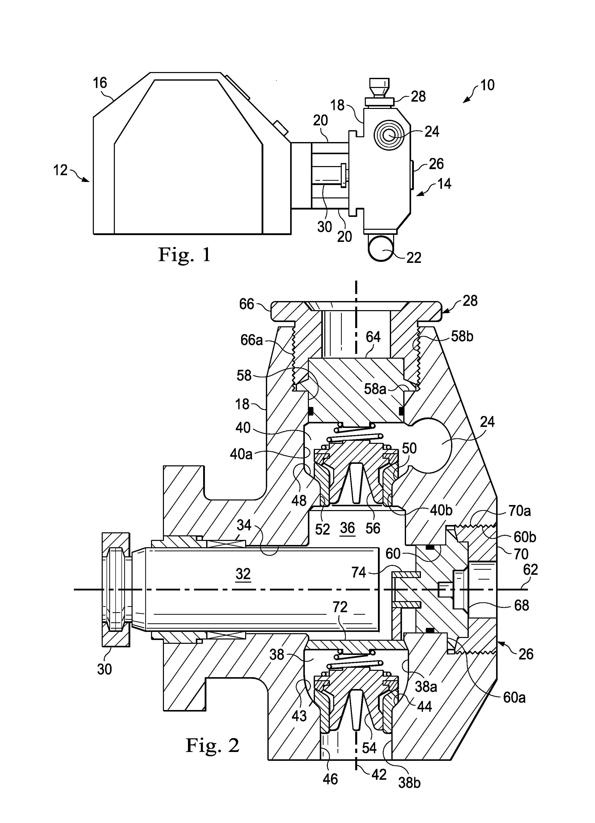
[0117]In an exemplary embodiment, as illustrated in FIG. 1, a reciprocating pump assembly is generally referred to by the reference numeral 10 and includes a power end portion 12 and a fluid end portion 14 operably coupled thereto. The power end portion 12 includes a housing 16 in which a crankshaft (not shown) is disposed, the crankshaft being operably coupled to an engine or motor (not shown), which is adapted to drive the crankshaft. The fluid end portion 14 includes a fluid end block 18, which is connected to the housing 16 via a plurality of stay rods 20. The fluid end block 18 includes a fluid inlet passage 22 and a fluid outlet passage 24, which are spaced in a parallel relation. A plurality of cover assemblies 26, one of which is shown in FIG. 1, is connected to the fluid end block 18 opposite the stay rods 20. A plurality of cover assemblies 28, one of which is shown in FIG. 1, is connected to the fluid end block 18 opposite the fluid inlet passage 22. A plunger rod assembl...
PUM
 Abstract
Description
Claims
Application Information