Apparatus and method

a technology of apparatus and well, which is applied in the direction of piston pumps, positive displacement liquid engines, borehole/well accessories, etc., can solve the problems of uneconomical wells with low production levels, and it is not feasible to deploy certain traditional pumping apparatuses to their subterranean depths

Inactive Publication Date: 2005-11-10
THAINSTONE ENERGY
View PDF14 Cites 40 Cited by
  • Summary
  • Abstract
  • Description
  • Claims
  • Application Information

AI Technical Summary

Benefits of technology

[0047] The pressure in the hydraulic conduit may be increased in order to break the shear pins and move the second piston along with the

Problems solved by technology

Because of the tight confines of wellbores, it is often not feasible to deploy certain traditional pumping apparatuses to their subterranean depths.
Therefore th

Method used


Image

  • Apparatus and method
  • Apparatus and method
  • Apparatus and method

Examples


Embodiment Construction

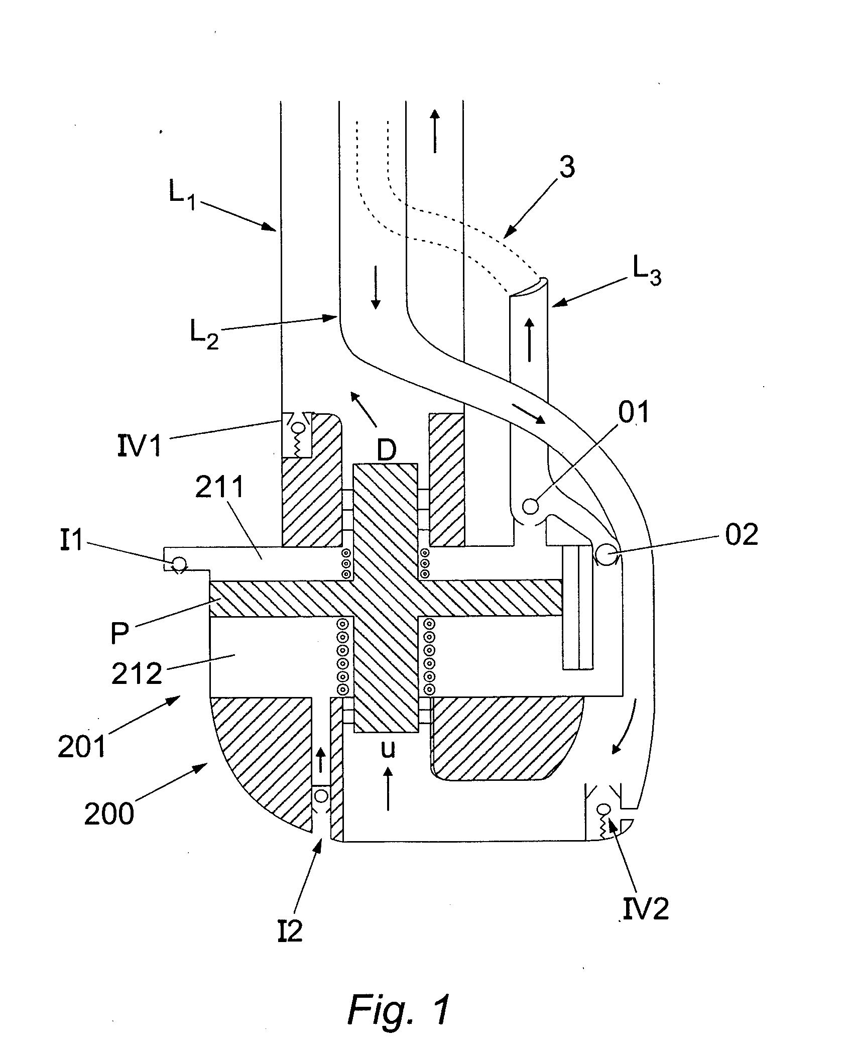
[0088] Referring initially to FIG. 1, a schematic hydraulic pump assembly 200 is shown. Pump assembly 200 preferably includes three hydraulic lines, L1, L2, and L3. L1 is shown as a hydraulic down-stroke operation line, L2 is shown as a hydraulic up-stroke operation line, and L3 is shown as a production fluid return line. While the lines are shown as three distinct lines, it should be understood by one of ordinary skill in the art that lines L1, L2, and L3 may be constructed as a single co-axial line having three distinct fluid flow passages. Pump assembly 200 includes a pump 201 with a hydraulic piston assembly P that reciprocates up and down within a housing of pump assembly 200. Piston P defines two pumping chambers, 211 and 212 and two pressure actuation surfaces U and D. Pressure from line L1 engages surface D and drives piston P down. As piston P is driven down, chamber 211 fills with production fluids through inlet valve I1 and production fluids within chamber 212 are forced ...


PUM


Abstract

The present invention includes methods and apparatuses to pump fluids from a well bore using a hydraulically actuated reciprocating pump to pump fluids from a well to the surface. In one embodiment the weight of the pumped fluid is utilised to return the piston in one direction and preferably the pressure within the well is utilised to urge the piston in the opposite direction thus reducing the amount of force required to reciprocate the piston and consequently reducing the amount of power required to operate the pump.

Description

RELATED APPLICATIONS [0001] This application is related to and claims priority from U.S. Provisional Application No. 60 / 567036, filed Apr. 30, 2004 and U.S. Provisional Application No. 60 / 609538, filed Sep. 13, 2004, the disclosures of which are incorporated herein by reference in their entirety.FIELD OF THE INVENTION [0002] This invention relates to an apparatus and method to recover fluids from a well and particularly but not exclusively to pump fluids from a gas well where fluid, such as water, hinders the release of the gas. However embodiments of the present invention may also be used to recover oil, particularly in low-producing wells with insufficient natural pressure to produce oil of their own accord. BACKGROUND OF THE INVENTION [0003] Production of hydrocarbon gas from wells is frequently prevented by the hydrostatic pressure of fluids, water and hydrocarbons which have entered the well bore. To cope with this, fluid is removed from the well using artificial lift methods i...

Claims


Application Information

Patent Timeline
IPC IPC(8): E21B43/00F04B17/00F04B35/00F04B47/00F04B47/04F04B47/08
CPCF04B47/08
Inventor JORDAN, LESLIE E.SMITH, DAVID R.
Owner THAINSTONE ENERGY
Why Eureka
Try Eureka