Connecting rod without wrist pin

a technology of connecting rods and wrist pins, which is applied in the direction of connecting rod bearings, positive displacement liquid engines, piston pumps, etc., can solve the problems of increasing the overall weight of the reciprocating pump, increasing the cost of transportation, and increasing the weight of the overall pump, so as to lighten the weight of the connecting rod and thereby the weight of the pump assembly

Inactive Publication Date: 2013-02-19
WEIR SPM
View PDF7 Cites 37 Cited by
  • Summary
  • Abstract
  • Description
  • Claims
  • Application Information

AI Technical Summary

Benefits of technology

[0006]In an embodiment of the present invention, a reciprocating pump assembly has a pump located inside a housing. The pump has a crankshaft that rotates and a crosshead that is connected to a plunger via a pony rod. The plunger pumps fluid through cylinders in the pump when it is moved longitudinally within the cylinder. A connecting rod has a body and connects at one endpiece to the crankshaft and at another endpiece to the crosshead to thereby translate the crankshaft's rotational movement into linear movement of the crosshead and thereby energize the plunger.
[0007]In this embodiment, the endpiece connected to the crosshead is secured to the crosshead by a bushing located within the crosshead. The bushing extends more than 180 degrees around the connecting rod's endpiece. The crosshead bushing allows the connecting rod's endpiece to pivot within the bushing during pump operation. To retain the connecting rod's endpiece within the bushing, a lock plate, support blocks, and retainers may be used. This eliminates the need for a wrist pin, resulting in one less part to service and repair. Further, the body and the endpiece of the connecting rod may be fabricated with hollow portions to lighten the weight of the connecting rod and thereby the weight of the pump assembly.

Problems solved by technology

Further, the wrist pin adds weight to the overall pump weight, which can make the transportation of reciprocating pumps more difficult and expensive.

Method used


Image

  • Connecting rod without wrist pin
  • Connecting rod without wrist pin
  • Connecting rod without wrist pin

Examples


Embodiment Construction

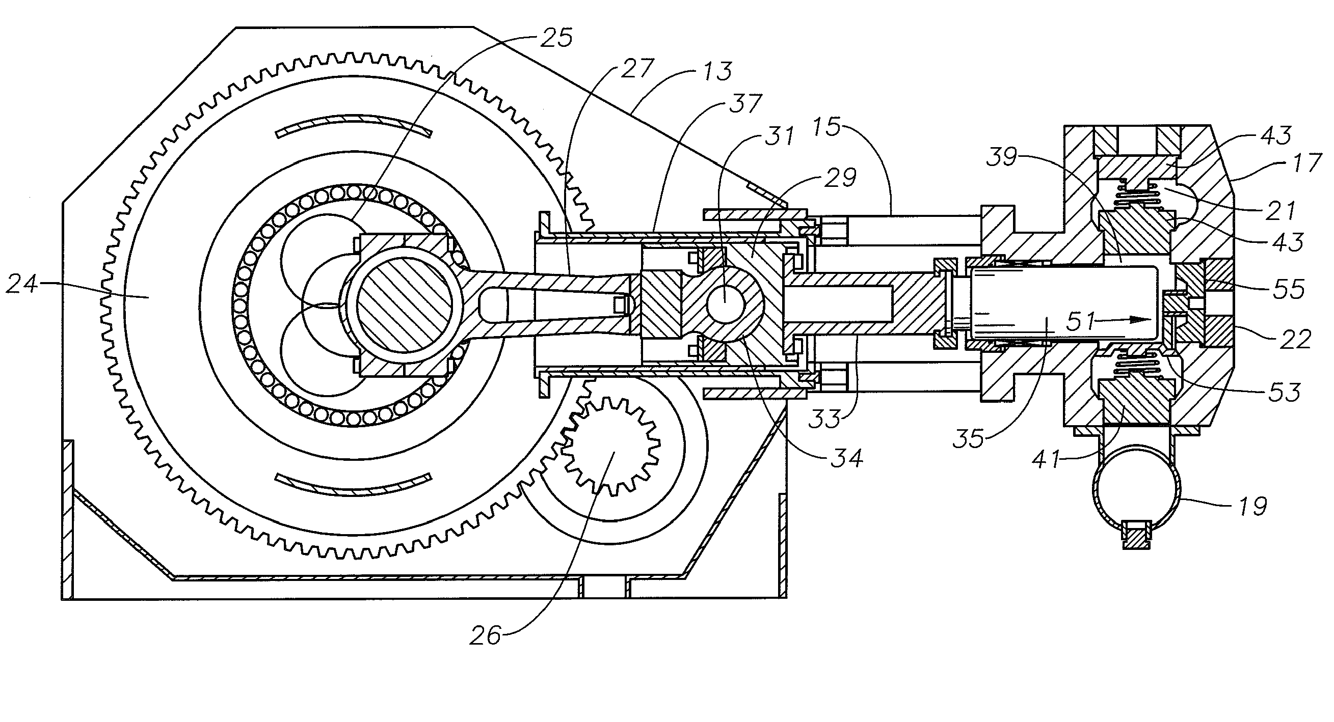
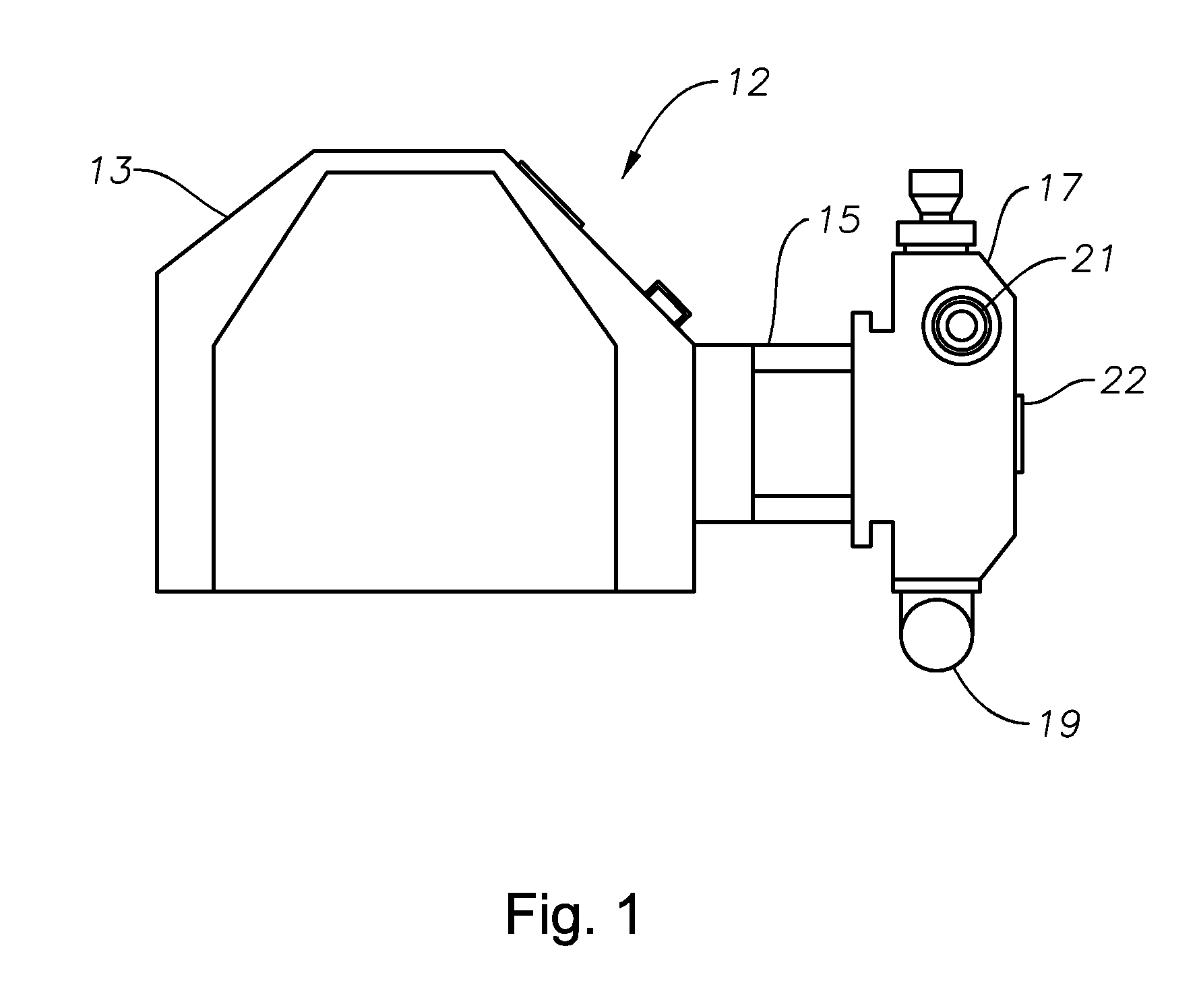
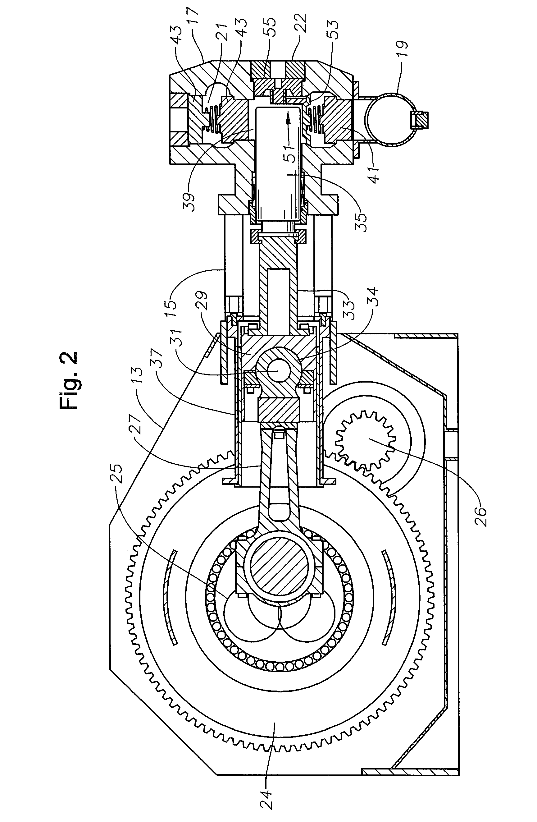
[0014]Referring to FIGS. 1 and 2, reciprocating pump assembly or pump 12 includes a crankshaft housing 13 that comprises a majority of the outer surface of reciprocating pump 12. Stay rods 15 connect crankshaft housing 13 to a set of cylinders 17. Each cylinder 17 is in communication with a fluid inlet 19 and a fluid outlet 21. As shown in FIGS. 1 and 2, a suction cover plate 22 connects to an end of each cylinder 17 opposite the plunger rod housing 15. Pump 12 can be free-standing on the ground, can be mounted to a trailer that can be towed between operational sites, or mounted to a skid such as for offshore operations.

[0015]Referring to FIG. 2, a portion of reciprocating pump 12 housed within crankshaft housing 13 is shown. Crankshaft housing 13 houses a crankshaft 25, which is typically mechanically connected to a motor (not shown). The motor rotates crankshaft 25 in order to drive reciprocating pump 12 (FIG. 1). In one embodiment, crankshaft 25 is cammed so that fluid is pumped ...


PUM


Abstract

A reciprocating pump assembly has a pump within a housing. The pump has a crankshaft that rotates and a crosshead that is connected to a plunger via a pony rod. The plunger pumps fluid through cylinders in the pump. A connecting rod connects at one end to the crankshaft and at another end to the crosshead to translate the crankshaft's rotational movement into linear movement of the crosshead and thereby the plunger. The end connected to the crosshead is secured to the crosshead by a bushing located within the crosshead that allows the connecting rod end to pivot during operation. The bushing extends more than 180 degrees, retaining the connecting rod with the crosshead without the need for a wrist pin. The end secured by the bushing can be retained within the bushing by a lock plate, and retainers without the need for a wrist pin.

Description

CROSS-REFERENCE TO RELATED APPLICATION[0001]This application claims priority to provisional application No. 61 / 143,300 filed Jan. 8, 2009.FIELD OF THE INVENTION[0002]This invention relates in general to connecting rods used in reciprocating pump crankshafts, and, in particular, to a connecting rod that does not require a wrist pin to link it to the crosshead.BACKGROUND OF THE INVENTION[0003]Connecting rods are used in various kinds of pumps used in oilfield operations. A connecting rod can be used, for example, in a reciprocating pump. The reciprocating pump can be used to pump fluid such as chemicals, cement, or other media into a well. Reciprocating pumps typically increase the pressure within a cylinder by reciprocating a plunger longitudinally within the cylinder. The connecting rod typically has a body and two ends. The crosshead end has a hole that allows the end to be connected to a crosshead, which is connected to a pony rod, which in turn is connected to the plunger. The ot...

Claims


Application Information

Patent Timeline
Patent Type & Authority Patents(United States)
IPC IPC(8): F04B53/10
CPCF04B9/045F04B53/147F16C9/04F16C5/00
Inventor KUGELEV, VLADIMIRMATZNER, MARK D.
Owner WEIR SPM
Why Eureka
Try Eureka