Lens barrel module and lens assembly including the same

a technology of lens barrel and lens assembly, which is applied in the direction of mountings, instruments, optics, etc., can solve the problems of time-consuming and complicated assembly procedures of conventional lens assemblies

Active Publication Date: 2017-01-05
GENIUS ELECTRONICS OPTICAL XIAMEN
View PDF7 Cites 5 Cited by
  • Summary
  • Abstract
  • Description
  • Claims
  • Application Information

AI Technical Summary

Benefits of technology

[0004]Therefore, an object of the disclosure is to provide a lens barrel module and a lens assembly that can alleviate at least one of the drawbacks of the prior arts.

Problems solved by technology

Hence, the assembly procedure of the conventional lens assemblies is complicated and time-consuming.

Method used


Image

  • Lens barrel module and lens assembly including the same
  • Lens barrel module and lens assembly including the same
  • Lens barrel module and lens assembly including the same

Examples


first embodiment

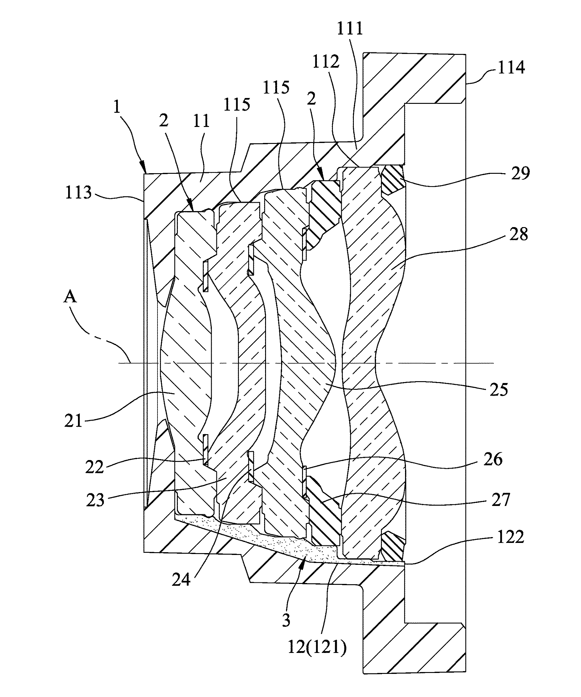
[0026]Referring to FIGS. 3 to 5, a lens assembly according to the disclosure includes a lens barrel module 1, a plurality of optical members 2 and an adhesive element 3.

[0027]The lens barrel module 1 includes a lens barrel unit 11 and a flow path unit 12.

[0028]The lens barrel unit 11 extends along an axis (A) and includes a peripheral wall 111 that surrounds the axis (A) and that has a first end 113 adjacent to an object side of the lens assembly and a second end 114 opposite to the first end 113 and adjacent to an image side of the lens assembly. The peripheral wall 111 defines an accommodation space 112 that is configured as a series of accommodation sections 115 arranged along the axis (A). Among the accommodation sections 115, one of the accommodation sections 115 that is most adjacent to the first end 113 has a sectional dimension not greater than another of the accommodation sections 115 that is most adjacent to the second end 114. In this embodiment, the accommodation section...

second embodiment

[0035]In the second embodiment, the accommodation sections 115 defined by the peripheral wall 111 of the lens barrel unit 11 of the lens barrel module 1 are grouped into an object side-adjacent accommodation area 116 and an image side-adjacent accommodation area 117.

[0036]The flow path unit 12 includes an object side-adjacent subunit 123 and an image side-adjacent subunit 124. The object side-adjacent subunit 123 includes three object side-adjacent flow paths 125 that are spacedly and angularly arranged and that are in spatial communication with the object side-adjacent accommodation area 116. Each of the object side-adjacent flow paths 125 has an opening 126 proximate to the second end 114. The image side-adjacent subunit 124 includes three image side-adjacent flow paths 127 that are spacedly and angularly arranged and that are in spatial communication with the image side-adjacent accommodation area 117. The image side-adjacent flow paths 127 are alternated with and not in spatial ...

third embodiment

[0039]In the third embodiment, the lens barrel unit 11 of the lens barrel module 1 includes an outer sleeve 118 and an inner sleeve 119. The outer sleeve 118 has a circumferential wall 110 that surrounds the axis (A) and defines a sleeve space 120. The inner sleeve 119 is disposed removably in the sleeve space 120 and includes the peripheral wall 111 that surrounds the axis (A), defines the accommodation space 112, and has the first and second ends 113, 114 and the accommodation sections 115. In this embodiment, the outer sleeve 118 and the inner sleeve 119 are exemplified by being secured to each other through an adhesive-dispensing and photocuring operation. However, other suitable securing techniques known in the relevant art are also applicable.

[0040]The flow path unit 12 includes a pair of flow paths 121, each of which is in spatial communication with the accommodation sections 115 and the sleeve space 120.

[0041]In this embodiment, the flow paths 121 of the flow path unit 12 ar...


PUM


Abstract

A lens barrel module is disclosed to include a lens barrel unit and a flow path unit. The lens barrel unit extends along an axis and includes a peripheral wall that surrounds the axis and that has a first end adjacent to an object side of a lens assembly and a second end opposite to the first end and adjacent to an image side of the lens assembly. The peripheral wall defines an accommodation space configured as a series of accommodation sections for receiving the optical members. The flow path unit is formed in the lens barrel module and is in spatial communication with at least two of the accommodation sections. A lens assembly including the lens barrel module is also disclosed.

Description

CROSS-REFERENCE TO RELATED APPLICATION[0001]This application claims priority of Chinese Patent Application No. 201510386503.1, filed on Jul. 3, 2015.FIELD[0002]The disclosure relates to a lens barrel module, and more particularly to a lens barrel module with an adhesive flow path. The disclosure also relates to a lens assembly including the lens barrel module with the adhesive flow path.BACKGROUND[0003]Referring to FIG. 1, a conventional lens assembly includes a lens barrel 4 and a plurality of optical members 5. The lens barrel 4 extends along an axis (B) includes a peripheral wall 41 that surrounds the axis (B), and has a first end 42 that is adjacent to an object side of the conventional lens assembly and a second end 43 that is opposite to the first end 42 and adjacent to an image side of the conventional lens assembly. The peripheral wall 41 defines an accommodation space 411 that is configured as a series of accommodation sections 44. The accommodation sections 44 have circula...

Claims


Application Information

Patent Timeline
Patent Type & Authority Applications(United States)
IPC IPC(8): G02B7/02
CPCG02B7/022G02B13/004G02B5/005G02B7/025G02B7/021
Inventor ZHAN, HAIBINCHO, HUNG-CHANGFU, WEIWEICHEN, ZHENMULI, WEIMIN
Owner GENIUS ELECTRONICS OPTICAL XIAMEN
Why Eureka
Try Eureka