Strut-type suspension device

a technology of suspension device and inclined member, which is applied in the direction of suspension, transportation and packaging, and resilient suspensions, etc., can solve the problems of increasing the number of parts, increasing the cost and weight of using inclined members, and impaired straight line travel, etc., and achieves the effect of easy induction and easy inclines of the bearing rotational axis

Active Publication Date: 2017-01-12
TOYOTA JIDOSHA KK
View PDF3 Cites 1 Cited by
  • Summary
  • Abstract
  • Description
  • Claims
  • Application Information

AI Technical Summary

Benefits of technology

[0009]The invention thus provides a strut-type suspension device having a structure that easily inclines a bearing rotational axis with respect to a shock absorber axis.
[0011]According to this aspect, the support surface for supporting the bearing is inclined with respect to the plane perpendicular to the shock absorber axis, so when the bearing is mounted to the support surface, the rotational axis of the bearing is able to be inclined with respect to the shock absorber axis. As a result, a rotational moment around a king pin axis is able to be suppressed, compared to when a rotational axis of the bearing is aligned with the shock absorber axis.
[0013]In the aspect described above, the mounting portion may include the support surface, and a protruding face disposed around an inner peripheral edge of the support surface, and an angle between the support surface and the protruding face may be greater than 90°. Also in the aspect described above, the angle between the support surface and the protruding face may be equal to or greater than the sum of an angle between the king pin axis and the shock absorber axis plus 90°. As a result, the bearing is able to be easily inserted onto the support surface of the mounting portion when assembling the shock absorber to the upper support.
[0014]According to this aspect of the invention, a strut-type suspension device having a structure that easily inclines a bearing rotational axis with respect to a shock absorber axis is able to be provided.

Problems solved by technology

When the upper spring seat and the lower spring seat rotate simultaneously, a rotational moment is generated around the king pin axis, and as a result, the ability to travel in a straight line is impaired.
Using this inclined member leads to an increase in the number of parts, and cost and weight due to using the inclined member increase, which is undesirable.
Moreover, in the assembly process of the suspension device, the inclined member must be properly assembled in a predetermined position in order to align the king pin axis with the bearing rotational axis, so assembly work is not easy.

Method used


Image

  • Strut-type suspension device
  • Strut-type suspension device
  • Strut-type suspension device

Examples


Embodiment Construction

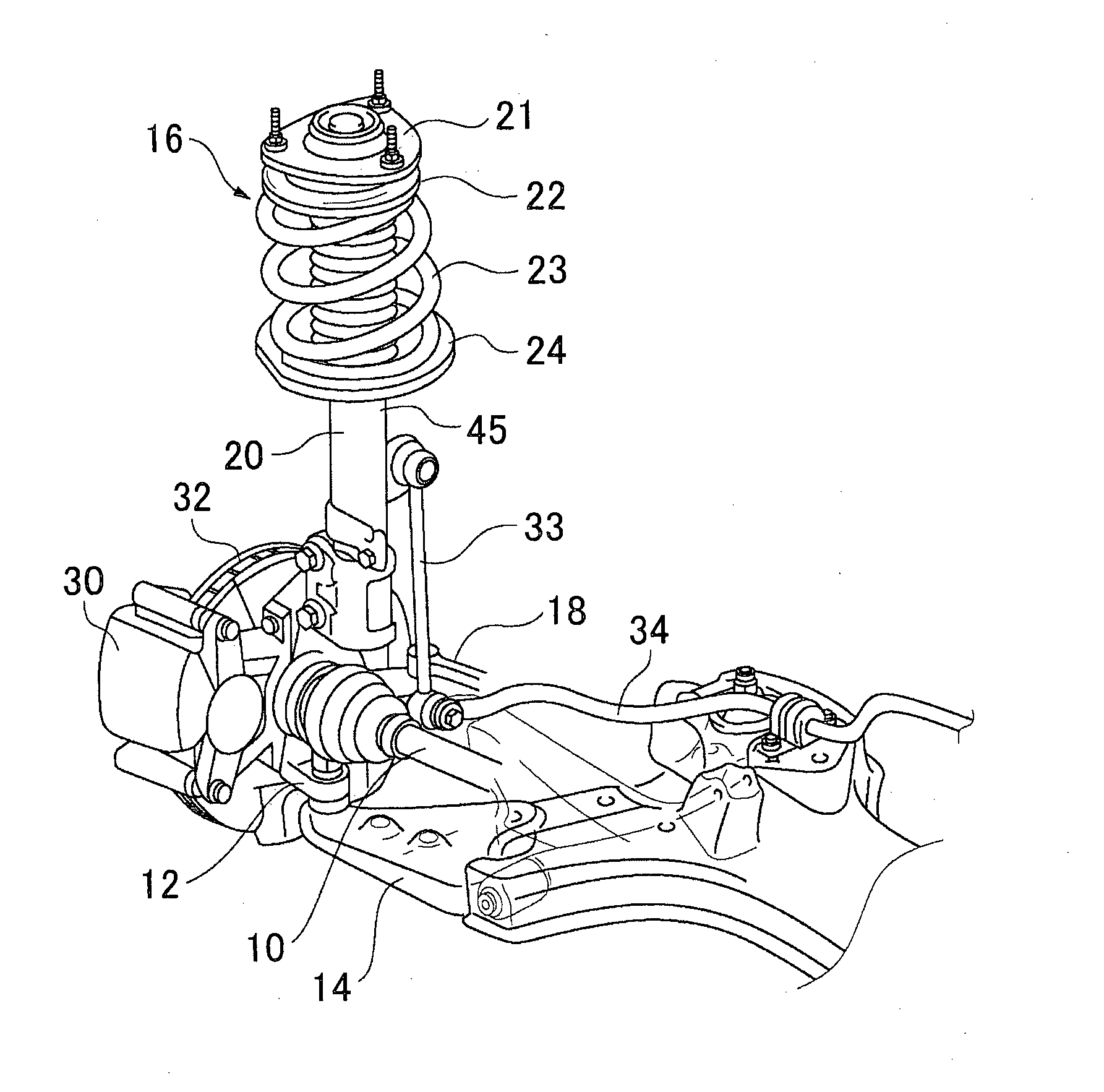
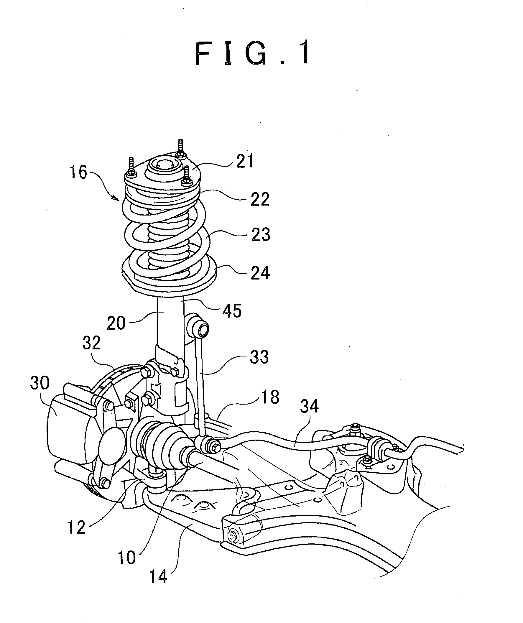
[0021]Hereinafter, example embodiments of the invention will be described with reference to the accompanying drawings. FIG. 1 is a perspective view of a strut-type suspension device according to one example embodiment of the invention, and the surrounding structure. The relationship between the strut-type suspension device of a wheel support device, and the surrounding structure, is described with reference to FIG. 1, and the details of the suspension device of the example embodiment will be described with reference to FIGS. 2 to 4.

[0022]The wheel support device includes a drive shaft 10 that transmits rotational driving force to a wheel, a knuckle 12 that rotatably supports the wheel, a lower arm 14 that connects the knuckle 12 to a vehicle body, and a suspension device 16.

[0023]An axle hub, not shown, that supports a wheel is inserted through the center portion of the knuckle 12. Also, a caliper 30 that forms a brake device is fixed to the knuckle 12. The caliper 30 includes a whe...


PUM


Abstract

A strut-type suspension device includes an upper support; a shock absorber that is supported by the upper support; a coil spring that is arranged surrounding the shock absorber, between an upper spring seat and a lower spring seat; and a bearing that is arranged between the upper spring seat and the upper support. The upper support includes a mounting portion that has a support surface for supporting the bearing. The support surface is inclined with respect to a plane perpendicular to a shock absorber axis.

Description

BACKGROUND OF THE INVENTION[0001]1. Field of the Invention[0002]The invention relates to a strut-type suspension device for a vehicle.[0003]2. Description of Related Art[0004]A strut-type suspension device in which a shock absorber also serves as a suspension support is known as one suspension device. The strut-type suspension device has a structure in which an upper end side of the shock absorber (strut) is mounted to a vehicle body side via a supporting member such as an upper support, and a lower end side of the shock absorber (strut) is mounted to a wheel side via a connecting member.[0005]In the strut-type suspension device, a coil spring is arranged surrounding the shock absorber. A lower end of the coil spring is supported by a lower spring seat that is fixed to a body of the shock absorber, and an upper end of the coil spring is supported by an upper spring seat. The upper spring seat is rotatably supported by the upper support via a bearing.[0006]The bearing is typically ar...

Claims


Application Information

Patent Timeline
Patent Type & Authority Applications(United States)
IPC IPC(8): B60G15/06
CPCB60G15/068B60G15/062B60G2204/418B60G2204/128B60G2204/1242
Inventor MURAKAMI, TAKAOHOMMA, YUJIASAOKA, NAOYA
Owner TOYOTA JIDOSHA KK
Why Eureka
Try Eureka