System and method for determining whether a cvt is set to a maximum gear ratio at vehicle startup

a technology of cvt and gear ratio, which is applied in the direction of gearing control, gearing elements, gearing wear, etc., can solve the problems of unsatisfactory wear of pulleys and/or drive belts, and the inability of angular velocity sensors used in cvts to provide accurate data

Active Publication Date: 2017-01-12
TOYOTA MOTOR ENGINEERING & MANUFACTURING NORTH AMERICA
View PDF3 Cites 3 Cited by
  • Summary
  • Abstract
  • Description
  • Claims
  • Application Information

AI Technical Summary

Benefits of technology

[0007]Described herein is a system for determining whether a transmission of a vehicle is set to a maximum gear ratio during startup. The system includes a continuously variable transmission (CVT) having a primary pulley assembly configured to receive power and including a primary fixed pulley and a primary sliding pulley. The CVT also includes a primary oil chamber coupled to the primary pulley assembly such that the pressure of oil within the primary oil chamber is applied to the primary pulley assembly. The CVT also includes a secondary pulley assembly including a secondary fixed pulley and a secondary sliding pulley. The CVT also includes a drive belt configured to transfer power from the primary pulley assembly to the secondary pulley assembly. The system also includes a pressure sensor coupled to the primary oil chamber and configured to detect a pressure of the oil within the primary oil chamber. The system also includes an electronic control unit coupled to the pressure sensor and configured to determine whether the CVT is set to the maximum gear ratio based on the detected pressure of the oil within the primary oil chamber.
[0008]Also described is a method for determining whether a CVT of a vehicle having a primary pulley assembly, a secondary pulley assembly, and an oil chamber coupled to the primary pulley assembly, is set to a maximum gear ratio. The method includes detecting, by a pressure sensor, a pressure of oil in the oil chamber. The method also includes determining, by an electronic control unit, a target pressure of the oil in the oil chamber. The method also includes determining, by the electronic control unit, whether the CVT is set to the maximum gear ratio based on a comparison of the detected pressure of the oil in the oil chamber and the target pressure of the oil in the primary oil chamber.
[0009]Also described is a method for protecting a drive belt of a CVT of a vehicle, the transmission having a primary pulley assembly, a secondary pulley assembly, and an oil chamber coupled to the primary pulley assembly. The method includes determining, by an electronic control unit, that an engine of the vehicle has started. The method also includes determining, by the electronic control unit, whether the CVT is in a park gear or a neutral gear. The method also includes determining, by a pressure sensor coupled to the oil chamber, a pressure of oil within the oil chamber. The method also includes determining, by the electronic control unit, whether the CVT is functioning at a maximum gear ratio based on the detected pressure of the oil in the oil chamber when the CVT is in the park gear or the neutral gear.

Problems solved by technology

This situation may arise during vehicle startup when oil pressure is not yet great enough to apply a sufficient force to the belt, causing undesirable wear of the pulleys and / or the drive belt.
However, angular velocity sensors used in CVTs may not provide accurate data while the angular velocity of the pulley assembly is below a predetermined amount, such as 150 revolutions per minute (rpm).

Method used


Image

  • System and method for determining whether a cvt is set to a maximum gear ratio at vehicle startup
  • System and method for determining whether a cvt is set to a maximum gear ratio at vehicle startup
  • System and method for determining whether a cvt is set to a maximum gear ratio at vehicle startup

Examples


Embodiment Construction

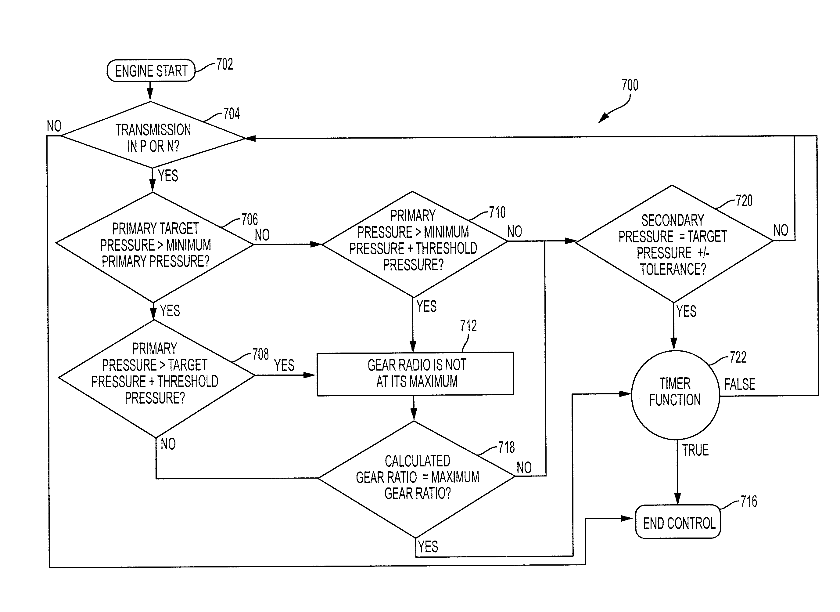
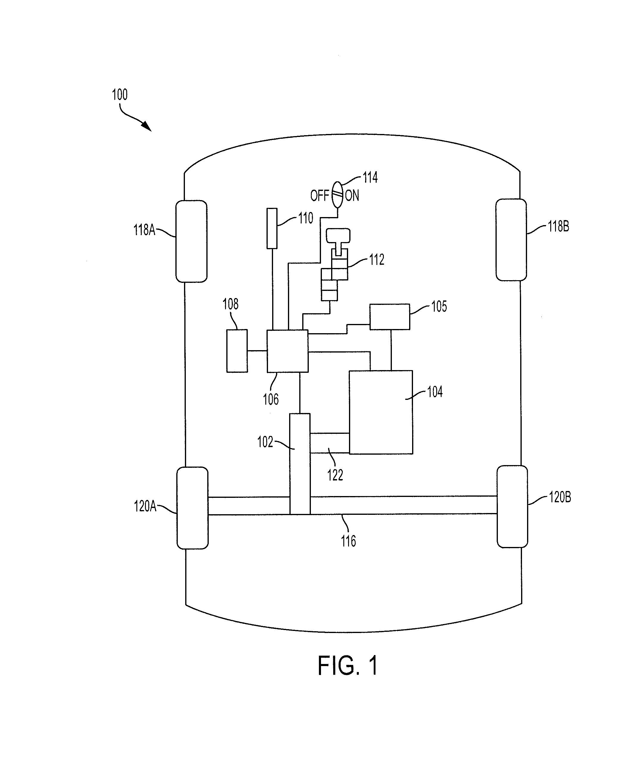
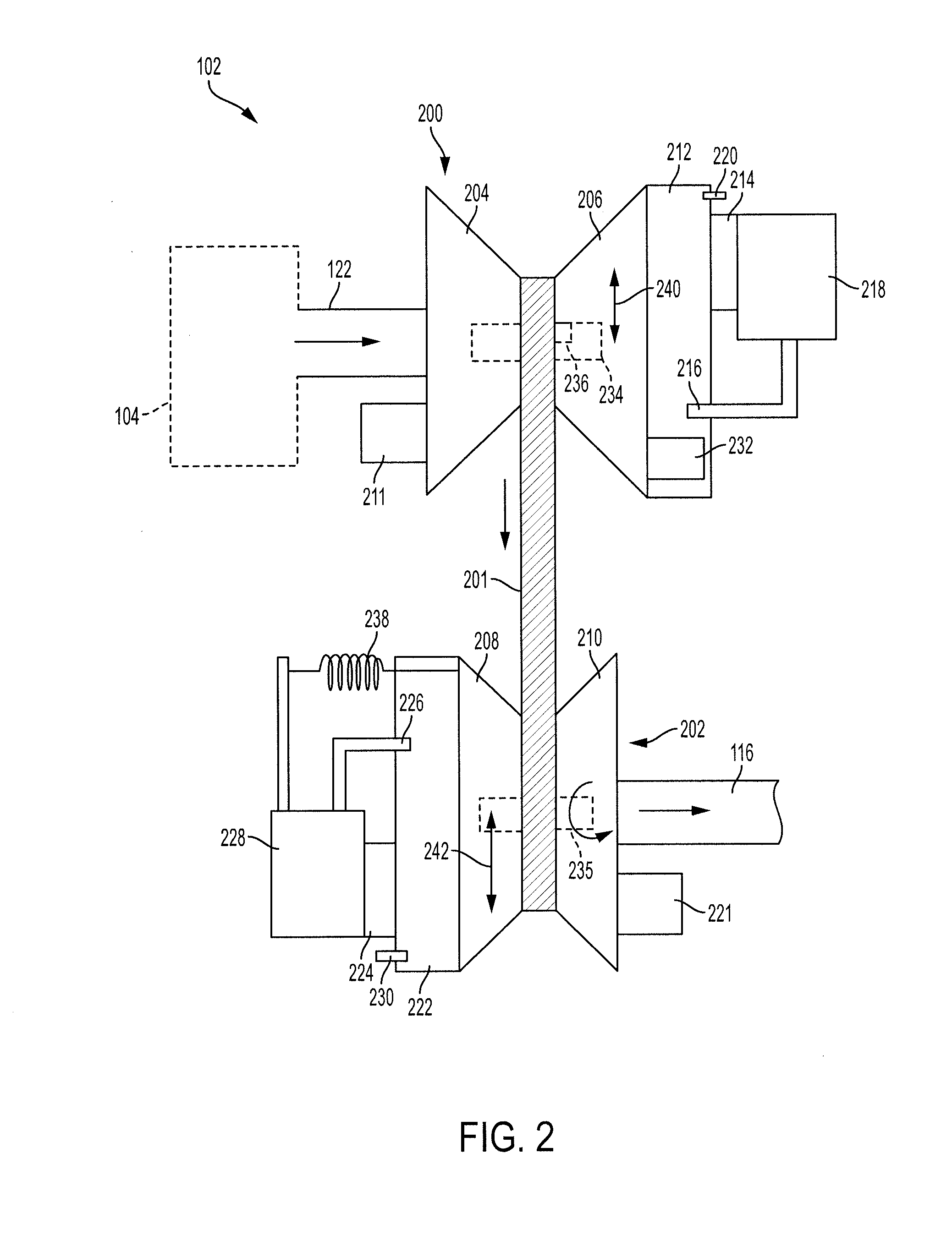
[0022]Disclosed herein are systems and methods for determining whether a continuously variable transmission (CVT) of a vehicle is set to a maximum gear ratio during and after startup of the vehicle. The systems include a CVT that utilizes variable diameter pulleys. In particular, the systems include a primary pulley assembly and a secondary pulley assembly each coupled to a drive belt such that power can be transferred from the primary pulley assembly to the secondary pulley assembly via the drive belt. A primary oil chamber is positioned adjacent to the primary pulley assembly and a secondary oil chamber is positioned adjacent to the secondary pulley assembly. In that regard, the gear ratio of the CVT may be changed by adjusting the pressures within each of the oil chambers. A pressure sensor is coupled to the primary oil chamber and can detect the pressure within the primary oil chamber. The systems also include an electronic control unit (ECU) that includes logic for determining ...


PUM


Abstract

A system includes a continuously variable transmission having a primary pulley assembly configured to receive power and a primary oil chamber coupled to the primary pulley assembly such that a pressure of oil within the primary oil chamber is applied to the primary pulley assembly. The continuously variable transmission also includes a secondary pulley assembly and a drive belt configured to transfer power from the primary pulley assembly to the secondary pulley assembly. The system also includes a pressure sensor coupled to the primary oil chamber and configured to detect a pressure of the oil within the primary oil chamber. The system also includes an electronic control unit coupled to the pressure sensor and configured to determine whether the continuously variable transmission is set to the maximum gear ratio based on the detected pressure of the oil within the primary oil chamber.

Description

BACKGROUND[0001]1. Field[0002]The present disclosure relates to a system and method for determining whether the gear ratio of a continuously variable transmission (CVT) that uses pulleys is set to a maximum gear ratio at startup based on detected pressures within oil chambers coupled to the pulleys.[0003]2. Description of the Related Art[0004]Various types of continuously variable transmissions, or CVTs, for automobiles have been introduced to the marketplace. One of these CVTs utilizes variable-diameter pulleys including a primary, or drive, pulley assembly that is mechanically coupled to an engine and / or a motor generator. The pulleys also include a secondary, or driven, pulley assembly that is mechanically coupled to an output device, such as an axle. The two pulley assemblies are typically aligned and a drive belt is coupled to and received by both pulley assemblies so power can be transferred from the primary pulley assembly to the secondary pulley assembly. The pulley assembli...

Claims


Application Information

Patent Timeline
Patent Type & Authority Applications(United States)
IPC IPC(8): F16H61/662F16H61/02F16H9/18
CPCF16H61/662F16H61/0204F16H9/18F16H61/66259F16H63/065
Inventor SATA, ANDREW G.
Owner TOYOTA MOTOR ENGINEERING & MANUFACTURING NORTH AMERICA
Why Eureka
Try Eureka