
Method and apparatus for scanning object

Active Publication Date: 2017-01-12
QUALITY VISION INT
View PDF2 Cites 20 Cited by
  • Summary
  • Abstract
  • Description
  • Claims
  • Application Information

AI Technical Summary

Benefits of technology

This patent describes a method and apparatus for scanning the surfaces of a three-dimensional object using two sensors. The first sensor has lower accuracy but faster data point acquisition, while the second sensor has higher accuracy but slower data point acquisition. The second sensor is used to acquire data points on the surfaces of the object before coating them. After coating, the first sensor is used to acquire subsequent data points on the surfaces, but these data points are then weighted based on the thickness of the coating to account for the impact on the accuracy of the sensor. This results in a cloud of three-dimensional coordinate points that is more accurate and reliable for use in various applications.

Problems solved by technology

However, current technologies for 3D area scanning may be adversely affected by surface finish, part geometry and feature size, resulting in a 3D point cloud with incorrect or insufficient information about various features of the part.
This is further complicated when those various features of the part are of particular interest.
Additionally, optical 3D area scanning devices are limited in how accurately they sense the features of the part, whereas it may be required to have information on portions of the part to a significantly greater degree of accuracy than provided by the area scanning device.
However, because they collect only one data point at a time, these devices result in relatively slow scans.
Thus, for efficient part quality evaluation, these devices may only be used practically in local areas of particular interest.
In other words, scanning the entire part with this type of device may be too slow, thus requiring one to compromise and omit some areas of the part.
The X-ray sensor is particularly inaccurate in determining the outer surface of a measured object; touch probes and optical image-processing sensors are designed to measure the surface.
The present inventors recognized such an approach applied to other high speed scanners such as 3D area scanners is not optimal because, unlike an X-ray scanner, 3D area scanners are surface scanners.
While not as accurate as the touch probe or optical image-processing sensor, the 3D area scanners do provide information about the surface of the measured object that should not be ignored.
Further, each of the two sensing technologies has different characteristics (e.g. point density), and to force one to overlay another may result in important information being lost.

Method used


Image

  • Method and apparatus for scanning object
  • Method and apparatus for scanning object

Examples


Embodiment Construction

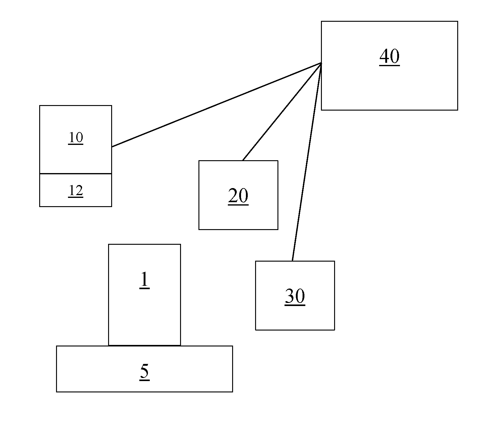
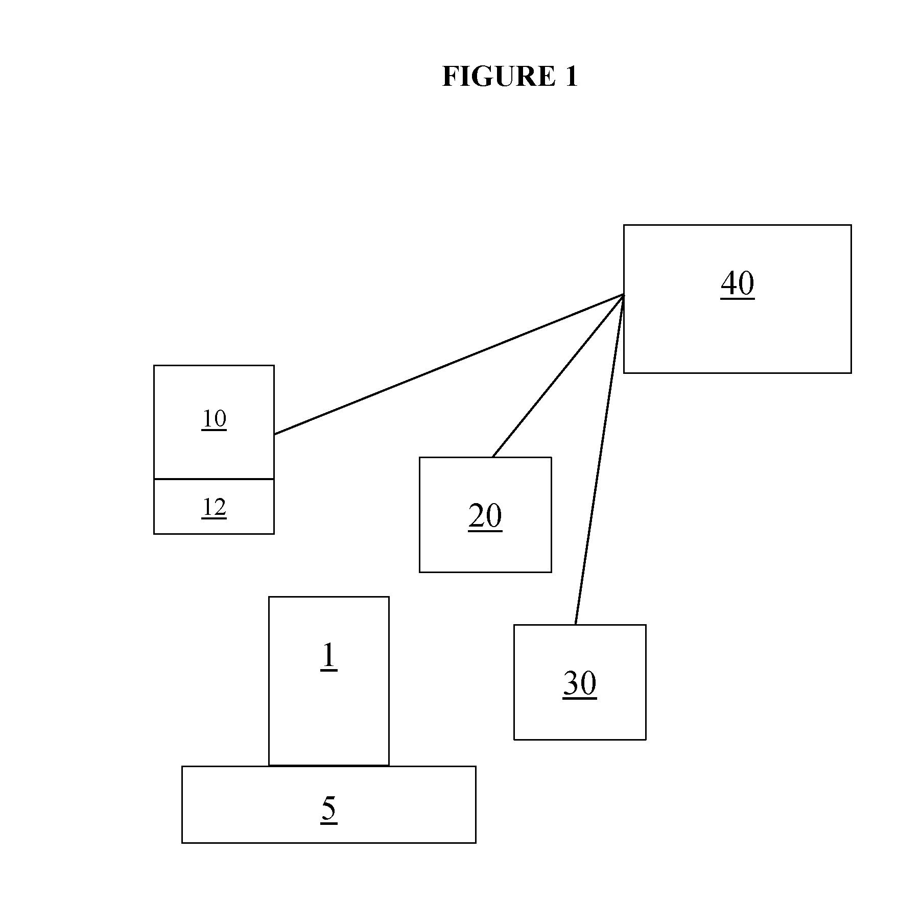
[0032]This invention provides improved 3D scanning methods, and apparatus for carrying out the methods. According to various embodiments, each of at least two different but complementary 3D scanning techniques generates 3D points. The 3D points from the at least two scanners are weighted differently, taking into account the accuracy of the respective 3D sensor, and are combined additively to supplement each other, yielding more accurate, complete 3D point clouds of scanned 3D objects, such as machined parts.

[0033]The method involves scanning surfaces of a 3D object with a first sensor to acquire first data points representative of the scanned surfaces, and adding the first data points to a 3D coordinate point cloud, and scanning surfaces of the 3D object with a second sensor to acquire second data points representative of the scanned surfaces, and adding the second data points to the 3D coordinate point cloud. The first sensor has a lower accuracy and a faster data point acquisition...


PUM


Abstract

Method and apparatus for scanning surfaces of a three-dimensional object employ a first sensor to acquire first data points and a second sensor to acquire second data points. The first sensor has a relatively lower accuracy and faster data point acquisition rate than the second sensor, and the second data points are assigned a higher weighting than the first data points. A three-dimensional coordinate point cloud is generated based on the both the first and second data points and their respective weighting.

Description

RELATED APPLICATIONS[0001]This application claims the benefit of priority to U.S. Provisional Patent Application Ser. No. 62 / 189,268, filed on Jul. 7, 2015, the content of which is relied upon and incorporated herein by reference in its entirety.STATEMENT REGARDING FEDERALLY SPONSORED RESEARCH OR DEVELOPMENT[0002]None.REFERENCE TO A “SEQUENCE LISTING”[0003]Not applicable.BACKGROUND OF THE INVENTION[0004]This invention relates to a method and apparatus for scanning an object. The invention is especially useful for an optical measurement system that inspects an object.[0005]Metrological machines are often employed for automated inspection of a manufactured object and for obtaining precise dimensional measurements of the manufactured object to ensure the object conforms to specifications.[0006]One type of inspection device is optical three-dimensional (3D) area scanners. Optical 3D area scanners provide relatively simple and quick access to large 3D point clouds, thereby allowing real-...

Claims


Application Information

Patent Timeline
IPC IPC(8): G01B11/00G01B11/25
CPCG01B11/25G01B11/002G01B5/008G01B5/066G01B11/0616G01B11/245
Inventor POLIDOR, EDWARD TARRYBLOOD, JEFFREYABBAS, DANIEL C.
Owner QUALITY VISION INT
Learn More