Conductive sheet for touch panel and capacitive touch panel

a capacitive touch panel and capacitive technology, applied in the field of capacitive touch panel and capacitive touch panel conductive sheets, can solve the problems of easy prevention and difficult to avoid disconnection, and achieve the effect of avoiding disconnection of detection electrodes and peripheral wirings, excellent followability, and effective prevention of disconnection in the bent portion

Active Publication Date: 2017-01-12
FUJIFILM CORP
View PDF7 Cites 19 Cited by
  • Summary
  • Abstract
  • Description
  • Claims
  • Application Information

AI Technical Summary

Benefits of technology

[0042]According to the invention, both of the detection electrodes and the peripheral wirings provided on the resin film are formed of the mesh having the thin conductive metal wires, the wire width of the first metal mesh constituting each of the detection electrodes is set to be equal to or less than 5 μm, and the extension direction of the thin conductive metal wires is inclined with respect to the bending line direction of the bent portion. The mesh has excellent followability when the resin film is extended. That is, the mesh extends comparatively easily to follow the extension locally occurr

Problems solved by technology

For this reason, it is not easy to prevent the local exten

Method used


Image

  • Conductive sheet for touch panel and capacitive touch panel
  • Conductive sheet for touch panel and capacitive touch panel
  • Conductive sheet for touch panel and capacitive touch panel

Examples


example 1

EXAMPLES 1 AND 2 AND COMPARATIVE EXAMPLES 1 TO 5

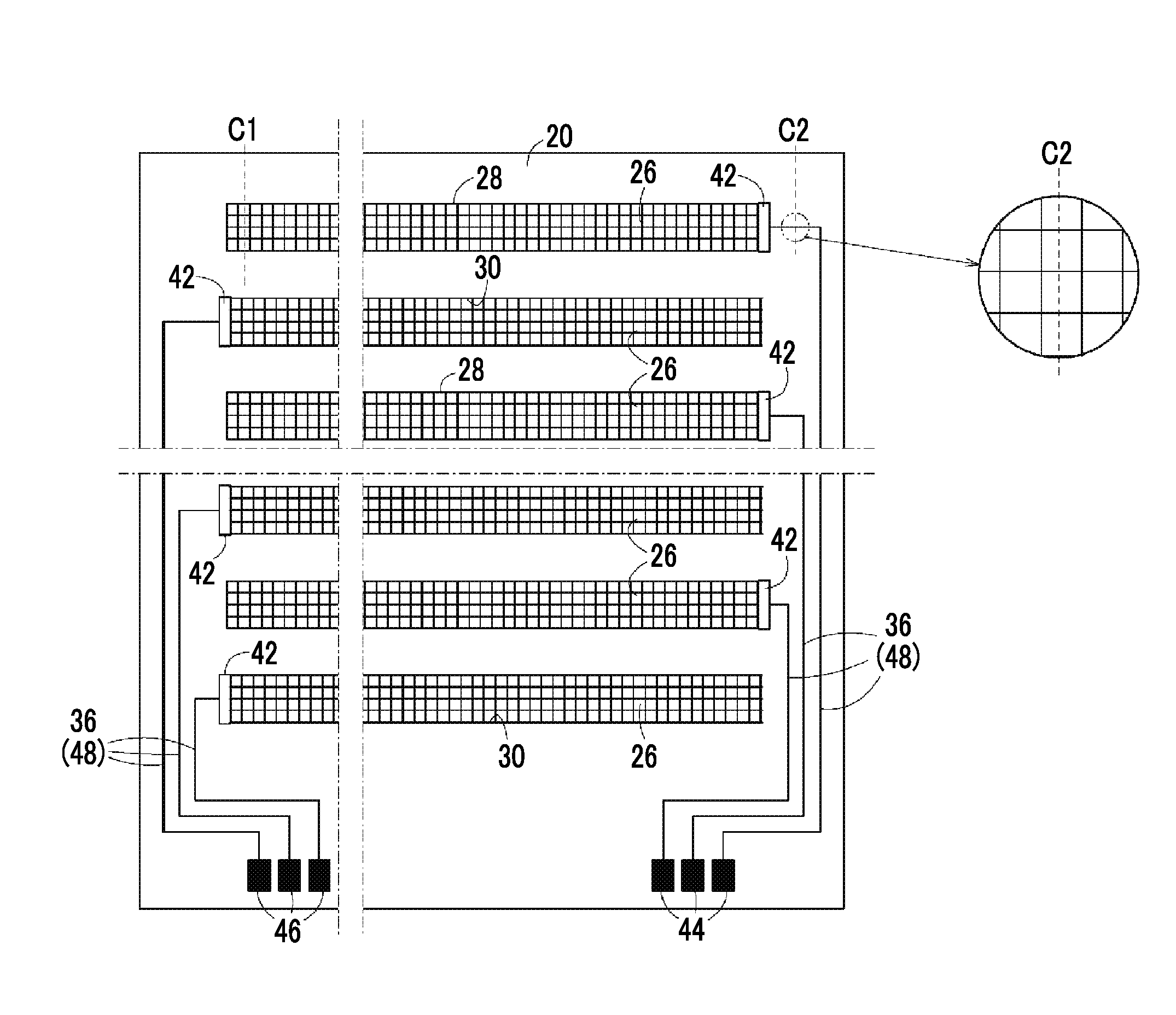
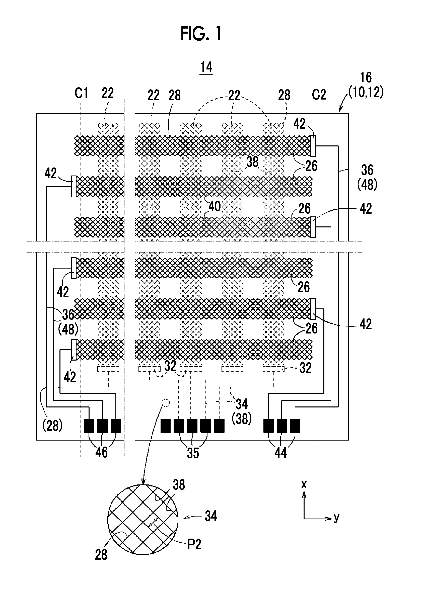
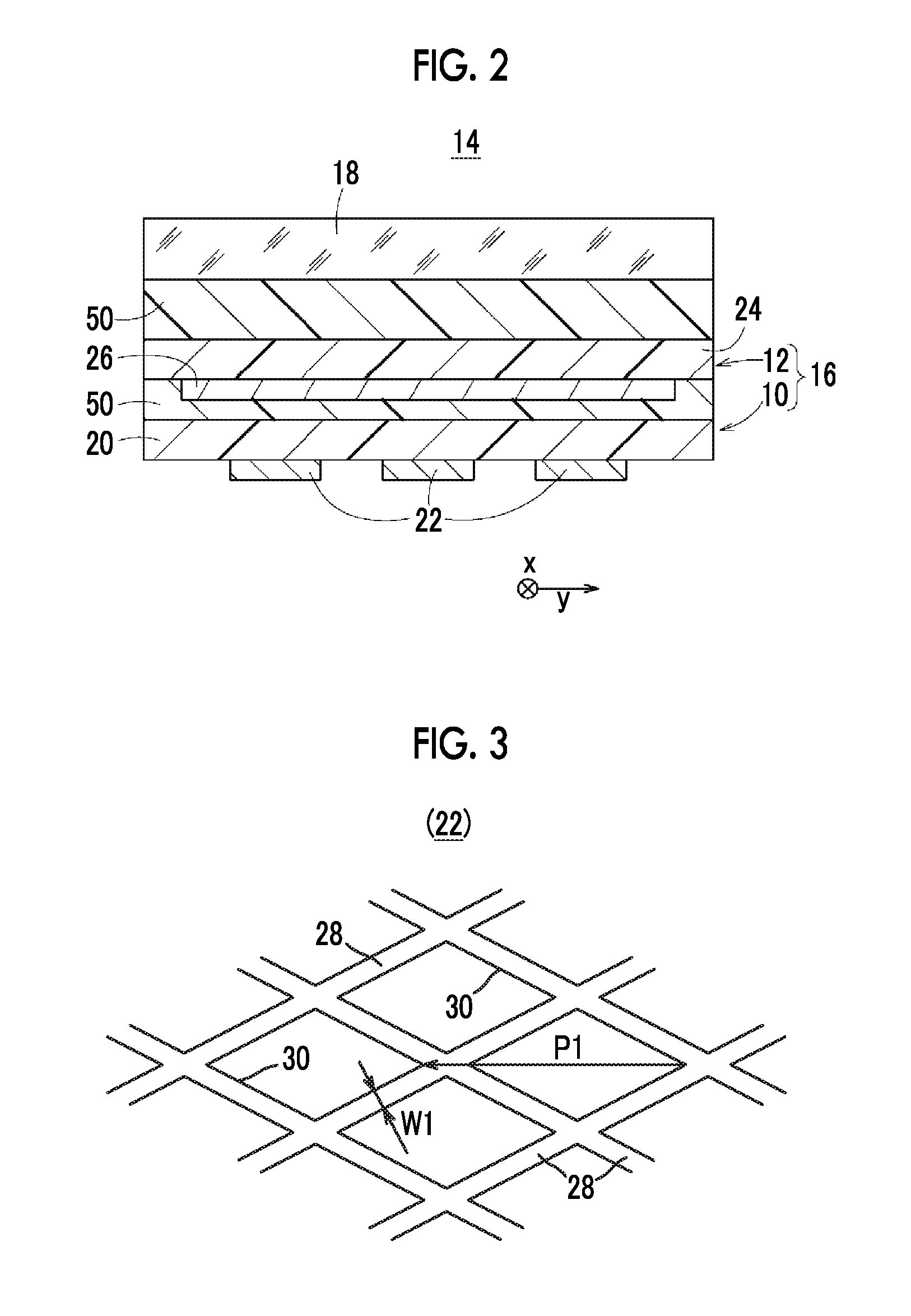
[0148]The conductive sheets 10 and 12 for a touch panel were produced according to the following method. The detection electrodes had a rhombic mesh shape made of silver see FIG. 5), the wire width was set to 4 μm, and the cell pitch was set to 200 μm. The terminal wiring portions (peripheral wirings) had a rhombic mesh shape made of silver, the wire width was set to 4 μm, and the cell pitch was set to 20 μm. The connection portions had a rhombic mesh shape made of silver, the wire width was set to 4 μm, and the cell pitch was set to 20 μm.

[0149]The detection electrodes, the connection portions, and the terminal wiring portions were formed simultaneously by patterning a silver thin film having a film thickness of 100 nm formed on a PET film having a film thickness of 100 μm using a sputter by a photolithography etching method. The film thickness of each of the detection electrodes, the connection portions, and the terminal wiring porti...

examples 3 to 6

[0163]A conductive sheet was produced based on Example 1 except that a stress distribution portion made of a silver mesh (wire width of 4 μm, pitch of 200 μm, and film thickness of 100 nm) using a sputtered thin silver film having the same mesh shape as the silver mesh constituting the detection electrode was interposed adjacent detection electrodes (see FIG. 8), and a touch panel was produced from the conductive sheet. This is referred to as Example 3.

[0164]In addition to the stress distribution portion interposed between adjacent detection electrodes, a stress distribution portion made of a silver mesh (wire width of 4 μm, pitch of 20 μm, and film thickness of 100 nm) using a sputtered thin silver film having the same mesh shape as the silver mesh constituting the peripheral wirings was interposed between adjacent terminal wiring portions. A conductive sheet shown in FIG. 9 was produced in the same manner as in Example 1 except for the above, and a touch panel was produced from th...

examples 7 to 14

[0170]A touch panel was produced while changing the inclination angle of the thin silver wires forming the mesh with respect to the bending lines C1 and C2 from 60° in the touch panel of Example 1 to any of 10°, 22.5°, 30°, 37.5°, 45°, 52.5°, 67.5°, or 80°. These are respectively referred to as Examples 7, 8, 9, 10, 11, 12, 13, and 14.

[0171]For the respective touch panels of Examples 7 to 14, disconnection fault, the sensitivity of the touch panel, and the visibility of the electrodes were evaluated. The results are collectively shown in Table 1. The specific evaluation details of the evaluation ranks “AA” to “C” relating to disconnection fault, sensitivity, and the visibility of the electrodes are as described above.

[0172]From Table 1, in all of Examples 7 to 14, it is understood that a touch panel has no disconnection observed, has sufficient sensitivity, and has visibility causing no problem. In particular, in Examples 8 to 13 in which the inclination angle was in a range of 20° ...


PUM


Abstract

In a second-conductive-sheet for a touch-panel, a plurality of upper-detection-electrodes disposed in a detection region and a plurality of second terminal wiring portions disposed in a peripheral wiring region to electrically connect the upper-detection-electrodes to second terminal portions and are formed. Each of the upper-detection-electrodes is made of a mesh-patterned first metal mesh having intersecting thin conductive metal wires, and each of the second terminal wiring portions is made of a mesh-patterned second metal mesh having intersecting thin conductive metal wires made of the same material as the thin conductive metal wires constituting each of the upper detection electrodes. The wire width of the first metal mesh is set to be equal to or less than 5 μm, and the extension direction of the thin conductive metal wires constituting the first metal mesh and the second metal mesh is inclined with respect to a bending line direction of a bent portion of a second-resin-film.

Description

CROSS-REFERENCE TO RELATED APPLICATIONS[0001]This application is a Continuation of PCT International Application No. PCT / JP2015 / 056787 Filed on Mar. 9, 2015, which claims priority under 35 U.S.C §119(a) to Japanese Patent Application No. 2014-102833 filed on May 16, 2014. Each of the above application(s) is hereby expressly incorporated by reference, in its entirety, into the present application.BACKGROUND OF THE INVENTION[0002]1. Field of the Invention[0003]The present invention relates to a conductive sheet for a touch panel which has a resin film, on which a plurality of detection electrodes and a plurality of peripheral wirings electrically connecting the detection electrodes to terminal portions are formed, and having a three-dimensional shape, and a capacitive touch panel.[0004]2. Description of the Related Art[0005]As a display device for a multi-function mobile phone (smartphone), a digital camera, or a personal computer, a so-called touch panel on which various operations a...

Claims


Application Information

Patent Timeline
IPC IPC(8): G06F3/044
CPCG06F3/044G06F2203/04111G06F2203/04112G06F2203/04103G06F3/04164G06F3/0445G06F3/0446G06F3/0448
Inventor NAKAYAMA, MASAYA
Owner FUJIFILM CORP
Why Eureka
Try Eureka