
Non-pneumatic tire

a technology of non-pneumatic tires and tires, which is applied in the direction of non-inflatable tires, vehicle components, transportation and packaging, etc., can solve the problem of structural unavoidable blowouts, and achieve the effect of reducing the deviation of ground pressure in the ground plan

Active Publication Date: 2017-01-19
BRIDGESTONE CORP
View PDF2 Cites 10 Cited by
  • Summary
  • Abstract
  • Description
  • Claims
  • Application Information

AI Technical Summary

Benefits of technology

The present invention aims to provide a non-pneumatic tire that can reduce stress concentration and deviation of ground pressure when a compressive force is applied in the tire radial direction.

Problems solved by technology

In a pneumatic tire of the related art that is filled with pressurized air and used, occurrence of a blowout is a structurally unavoidable problem.

Method used


Image

  • Non-pneumatic tire
  • Non-pneumatic tire
  • Non-pneumatic tire

Examples


example 1

[0111]Elastic deformation of the non-pneumatic tire can be further increased. In addition, a portion of attenuating stress is reduced because a large width section of the non-pneumatic tire is short, reduction in weight is possible, and the elastic deformation is secured.

example 2

[0112]Elastic deformation can be further increased while maintaining attenuation of stress of the non-pneumatic tire.

example 3

[0113]A balance between a degree of elastic deformation and attenuation of the stress of the non-pneumatic tire is good.


PUM


Abstract

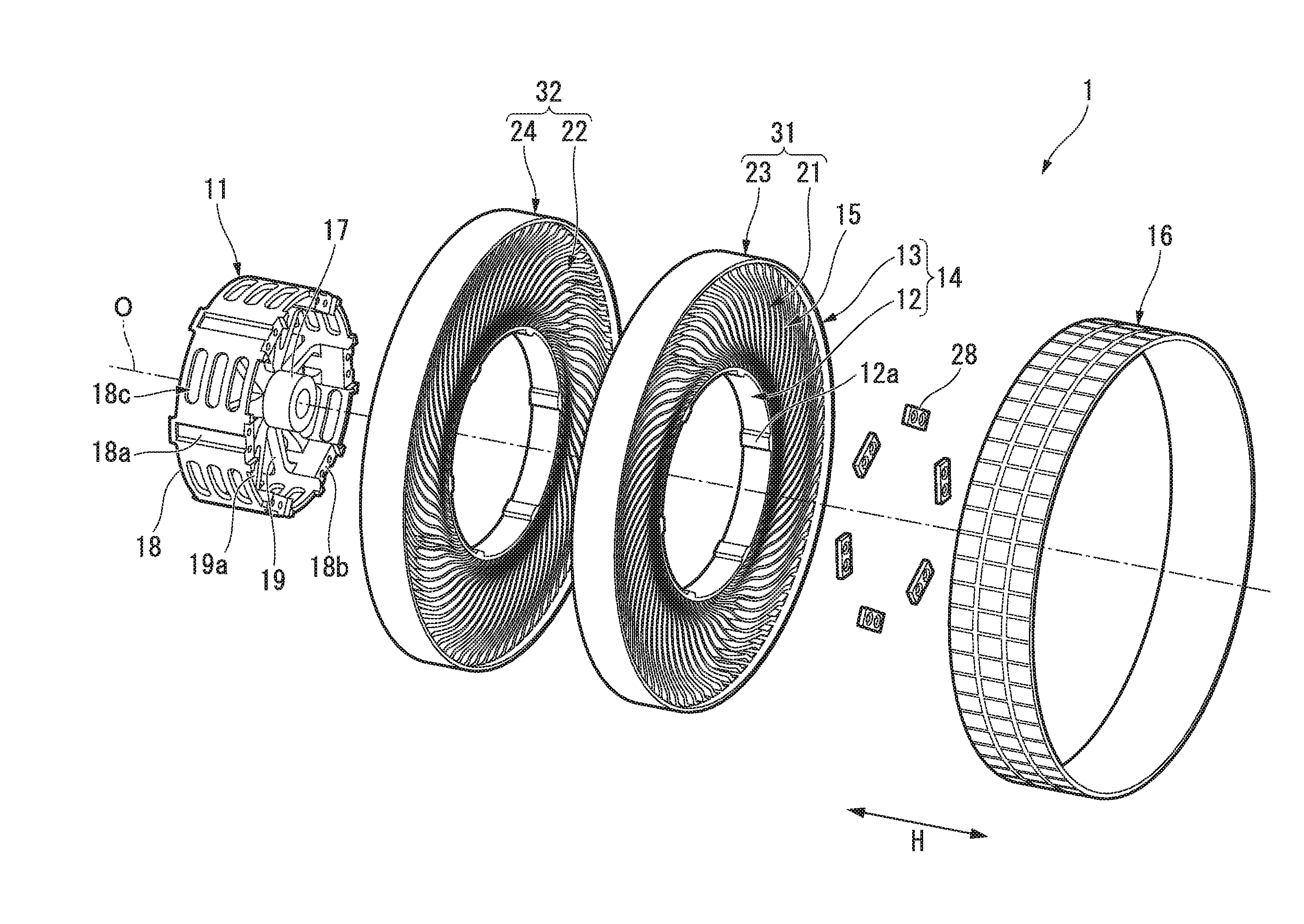
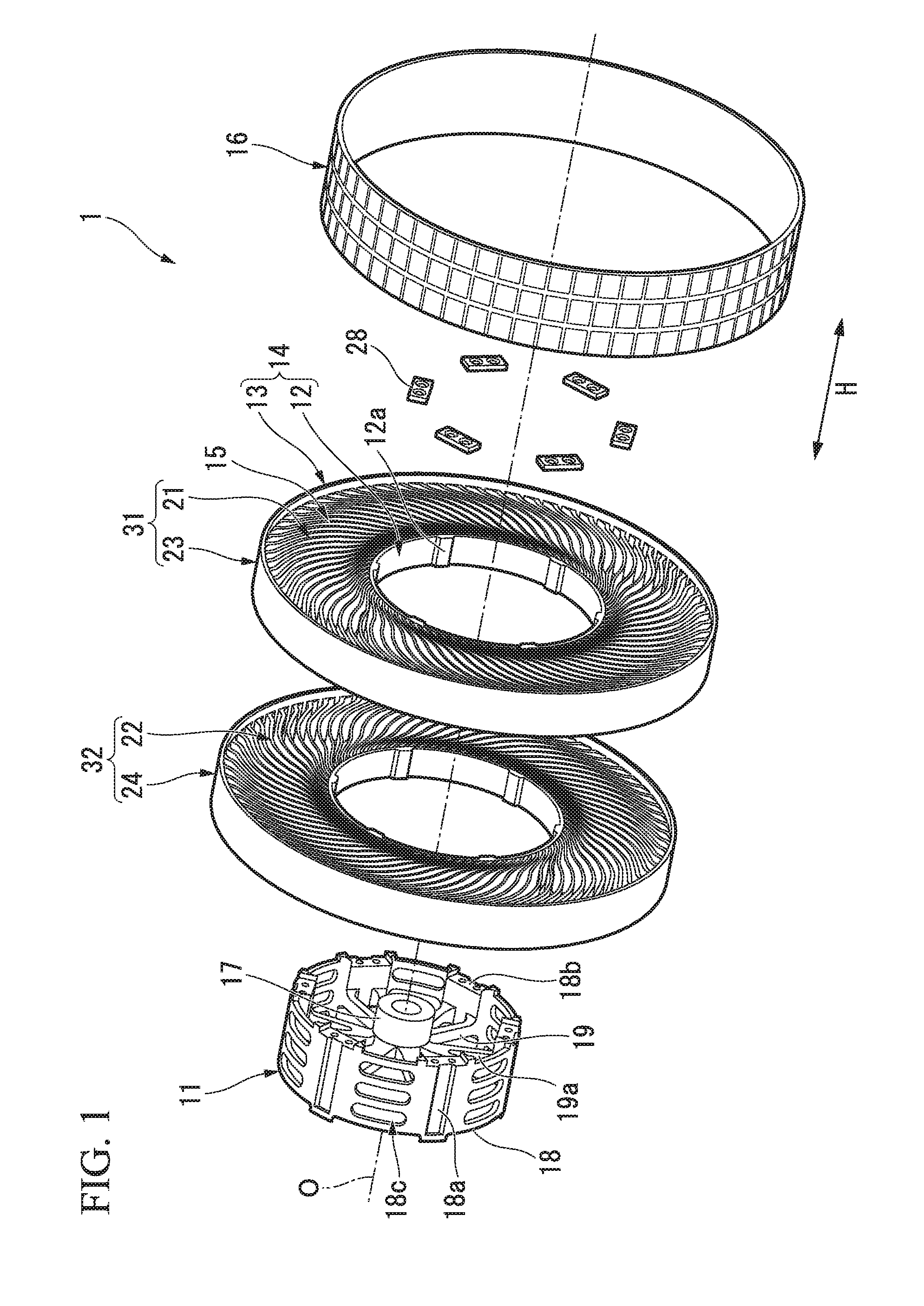
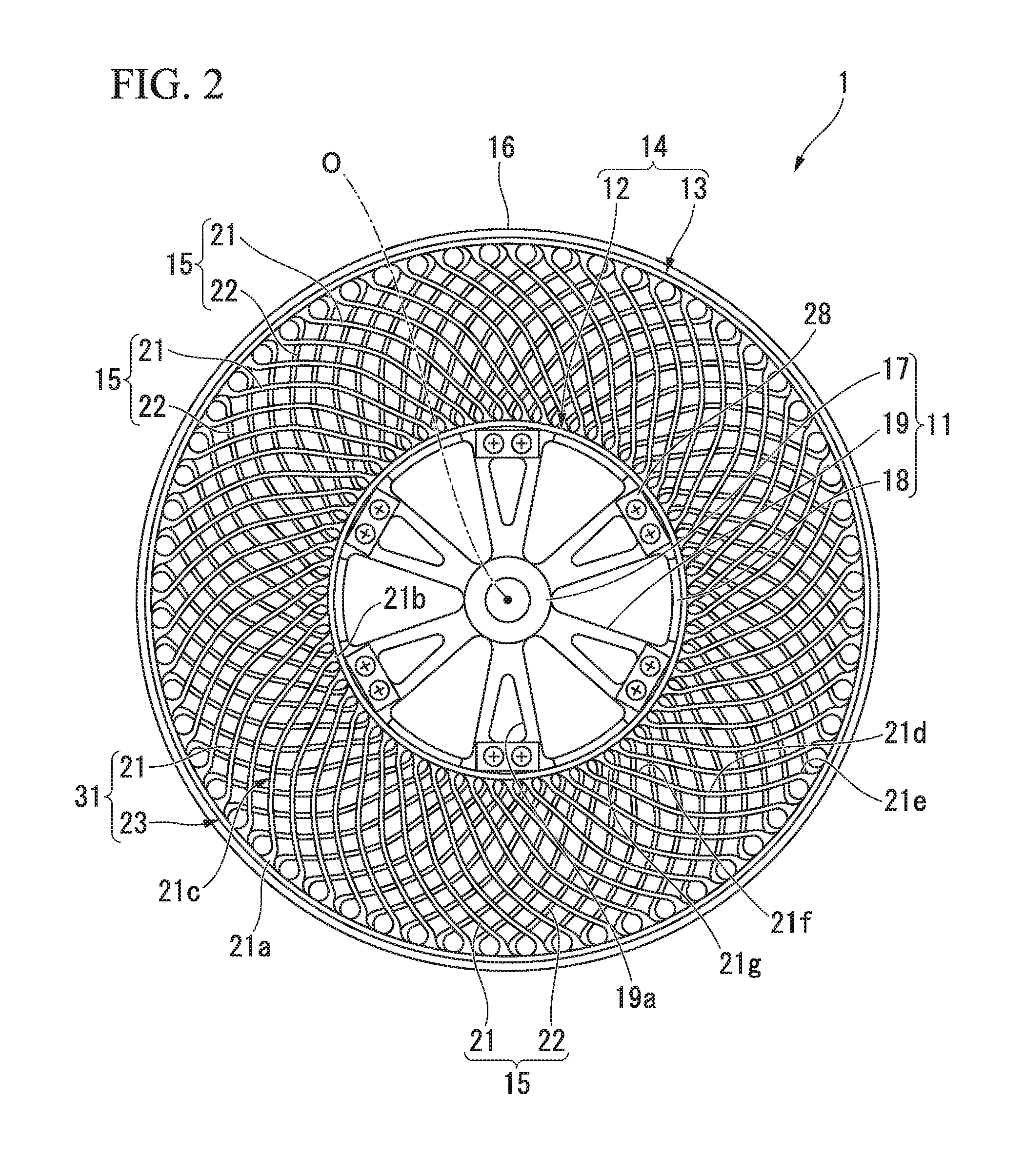
Provided is a non-pneumatic tire including an attachment body attached to an axle, an outer tubular body (13) configured to surround the attachment body from the outside in a tire radial direction, and a connecting member (15) configured to connect the attachment body and the outer tubular body while allowing displacement therebetween, wherein the connecting member includes a first elastic connecting plate (21) in which a first end portion (21a) connected to the outer tubular body is disposed closer to a first side in a tire circumferential direction than a second end portion connected to the attachment body and an intermediate portion (21c) is disposed between the first end portion and the second end portion, and both of circumferential end surface (26a, 26b) directed in the tire circumferential direction among surfaces of the first end portion of the first elastic connecting plate extend in opposite directions in the tire circumferential direction to be separated from each other from the inside toward the outside in the tire radial direction.

Description

TECHNICAL FIELD[0001]The present invention relates to a non-pneumatic tire that can be used without being filled with pressurized air.[0002]Priority is claimed on Japanese Patent Application No. 2014-53571, filed Mar. 17, 2014, the content of which is incorporated herein by reference.BACKGROUND ART[0003]In a pneumatic tire of the related art that is filled with pressurized air and used, occurrence of a blowout is a structurally unavoidable problem.[0004]In order to solve this problem, in recent years, for example, as disclosed in the following Patent Document 1, a non-pneumatic tire including an attachment body attached to an axle, an outer tubular body configured to surround the attachment body from the outside in a tire radial direction, and connecting members configured to connect the attachment body and the outer tubular body while allowing displacement therebetween has been proposed.[0005]In addition, in the non-pneumatic tire, the connecting members include an elastic connecti...

Claims


Application Information

Patent Timeline
Patent Type & Authority Applications(United States)
IPC IPC(8): B60C7/24B60C7/14
CPCB60C7/24B60C2007/146B60C7/14B60C7/18B60C7/20B60C7/146
Inventor SHOJI, TAKANORIABE, AKIHIKO
Owner BRIDGESTONE CORP
Learn More