
Trestle with postpositive drive and method of installing and adjusting

A trestle bridge and main bridge technology, applied to bridges, bridge forms, shaft equipment, etc., can solve the problems of slow construction progress, low construction efficiency, waste of materials, etc., and achieve the effects of ensuring safety, reliable connection, and stable support

Pending Publication Date: 2018-05-18
CHENGDU RUIHE MACHINERY MFG
View PDF0 Cites 3 Cited by
  • Summary
  • Abstract
  • Description
  • Claims
  • Application Information

AI Technical Summary

Problems solved by technology

[0008] The purpose of the present invention is: for the structure of the trestle bridge in the prior art, the main bridge is horizontally arranged, the length of the main bridge is roughly the same as the length of the front approach bridge, and the length of the rear approach bridge is longer, the waste of materials and the construction space are short and narrow, which leads to For the problems of low construction efficiency and slow construction progress, a driving rear trestle and installation and adjustment methods are provided. The driving rear trestle changes the overall structural form of the existing trestle, greatly increases the length of the front approach bridge, and shortens the rear bridge. The length of the approach bridge expands the scope of the construction area for laying inverted arch formwork and pouring concrete, and the construction space becomes spacious, which further improves the construction efficiency while ensuring that construction vehicles can pass through the trestle bridge smoothly and safely

Method used


Image

  • Trestle with postpositive drive and method of installing and adjusting
  • Trestle with postpositive drive and method of installing and adjusting
  • Trestle with postpositive drive and method of installing and adjusting

Examples


Embodiment 1

[0126] The driving rear trestle of this embodiment is applied in the process of tunnel construction.

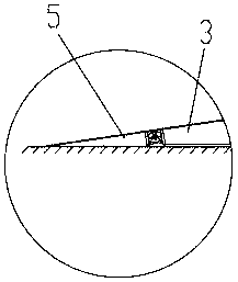
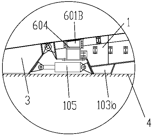
[0127] drive rear trestles, such as figure 1 , figure 2 , image 3 and Figure 4 As shown, it includes the main bridge 1 arranged on the support surface 4, the angle between the bridge deck of the main bridge 1 and the support surface is an acute angle, and the front end and the rear end of the main bridge 1 are connected to the front approach bridge 2 and the rear bridge respectively. Approach bridge 3, described front approach bridge 2 comprises inclined section 201 and horizontal section 202, and the deck of described inclined section 201 forms an acute angle with horizontal plane, and described horizontal section 202 is connected with main bridge 1, and the length of described front approach bridge 2 is longer than main bridge The length of bridge 1. The supporting surface 4 is a lined concrete surface, that is, the filling surface of the inverted arch in the tunnel....

Embodiment 2

[0138] The driving rear trestle of the present embodiment is roughly the same as embodiment 1, and the trestle foundation of embodiment 1 is provided with walking device, as Figure 5 , Figure 6 , Figure 7 , Figure 8 , Figure 9 , Figure 10 and Figure 28 As shown, the left and right ends of the main bridge 1 are provided with a lifting mechanism 603, and the lower part of the lifting mechanism 603 is provided with a running device 7. The running device 7 includes a track 701 and a supporting running mechanism 71. Connected with the main bridge 1, the traveling device 7 also includes a telescopic mechanism 702 connected at one end to the traveling mechanism 71, and the other end of the telescopic mechanism 702 is connected with a fixing device 8 installed on the track, and the fixing device 8 is detachable connected to track 701. The traveling mechanism 71 can be driven to move by stretching or shortening the telescopic mechanism 702. When the fixing device 8 is sepa...

Embodiment 3

[0146] The drive rear trestle of the present embodiment is roughly the same as embodiment 1, and the trestle foundation of embodiment 1 is provided with traverse device 6, as Figure 5 , Figure 11 and Figure 12 As shown, the traversing device 6 is installed on the main bridge 1, and the traversing device 6 includes a connecting rod 601 arranged under the main bridge 1, and a sliding connection between the connecting rod 601 and the main bridge 1, the connection A translation mechanism 602 is connected between the rod 601 and the main bridge 1 , one end of the translation mechanism 602 is connected to the main bridge 1 , and the other end is connected to the connecting rod 601 , and the two ends of the connecting rod 601 are respectively connected to a lifting mechanism 603 .

[0147] As one of the implementation manners, the lifting mechanism 603 is a vertically arranged oil cylinder, the cylinder barrel of the oil cylinder is connected with the connecting rod 601 , and the...


PUM


Abstract

The invention relates to the technical field of tunnel construction, in particular to a trestle with a postpositive drive and a method of installing and adjusting. The trestle with the postpositive drive includes a main bridge which is arranged on a support surface, and the included angle between the bridge face of the main bridge and the support surface is sharp. The front and rear ends of the main bridge are correspondingly connected with a front approach bridge and a rear approach bridge. The front approach bridge includes an inclined section and a horizontal section, and the included anglebetween the bridge face of the inclined section and a horizontal face is sharp. The horizontal section is connected with the main bridge, and the length of the front approach bridge is longer than the length of the main bridge. The overall structural form of the existing trestle is changed, the length of the front approach bridge is greatly increased, and the length of the rear approach bridge isshortened. Therefore the construction area scope of paving an inverted arch template and pouring concrete is enlarged, the construction space is become spaciously, and the construction efficiency isfurther improved by ensuring that a construction vehicle can pass through the trestle smoothly and safely.

Description

technical field [0001] The invention relates to the technical field of tunnel construction, in particular to a driving rear trestle and an installation and adjustment method. Background technique [0002] During tunnel construction, when the front of the tunnel is excavated, the stones produced need to be transported out through the rear, followed by construction and filling of concrete. During the construction of the inverted arch to fill the concrete, the passage of the ballasting vehicle is blocked. At this time, it is necessary to use the trestle bridge to cross the inverted arch to fill the concrete construction area, so that the ballasting vehicle can pass through the trestle bridge, and at the same time, the engineers are working under the trestle bridge. [0003] There are many types of trestle bridges used in tunnel construction. The relatively simple trestle bridge is a structure spliced ​​by I-beams. Separation requires laying formwork separately, and the constru...

Claims


Application Information

Patent Timeline
IPC IPC(8): E01D15/10E21D11/10E21D9/12
CPCE21D9/12E21D11/10E01D15/10Y02A30/60
Inventor 谢玉军陈煜王明光廖桦
Owner CHENGDU RUIHE MACHINERY MFG
Learn More