Thrust vectoring on a rotor-based remote vehicle

a remote vehicle and rotor technology, applied in vehicle position/course/altitude control, process and machine control, instruments, etc., can solve the problems of insufficient control system for achieving and maintaining flight stability, deficient sensors, slowing the wide-spread use and adoption of rotor-based drones, etc., to reduce drag, increase the range and speed of a particular rotor-based remote flying vehicle platform, and minimize the effect of drag

Active Publication Date: 2017-01-19
UAVPATENT CORP
View PDF4 Cites 33 Cited by
  • Summary
  • Abstract
  • Description
  • Claims
  • Application Information

AI Technical Summary

Benefits of technology

[0006]Embodiments disclosed herein comprise systems, methods, and apparatus configured to provide a rotor-based remote flying vehicle platform with thrust vectoring. In particular, disclosed embodiments comprise rotor-based remote flying vehicle platforms with motors that comprise at least single-axis variable tilting motors. Depending upon desired flight characteristics, the motors can be properly tilted to increase directional thrust and to minimize drag caused by the vehicle frame. As such, the range and speed of a particular rotor-based remote flying vehicle platform can be significantly increased by properly manipulating the tilt of the motors.

Problems solved by technology

Several technical limitations have slowed the wide-spread use and adoption of rotor-based drones.
These technical limitations include insufficient control systems for achieving and maintaining flight stability, deficient sensors for accurately obtaining positional data for the rotor-based drones, and high-power usage that both limited the flight time of rotor-based drones and increase their weight from batteries.
As such, there are several problems in the art to be addressed.

Method used


Image

  • Thrust vectoring on a rotor-based remote vehicle
  • Thrust vectoring on a rotor-based remote vehicle
  • Thrust vectoring on a rotor-based remote vehicle

Examples


Embodiment Construction

[0019]The following discussion now refers to a number of methods and method acts that may be performed. Although the method acts may be discussed in a certain order or illustrated in a flow chart as occurring in a particular order, no particular ordering is required unless specifically stated, or required because an act is dependent on another act being completed prior to the act being performed.

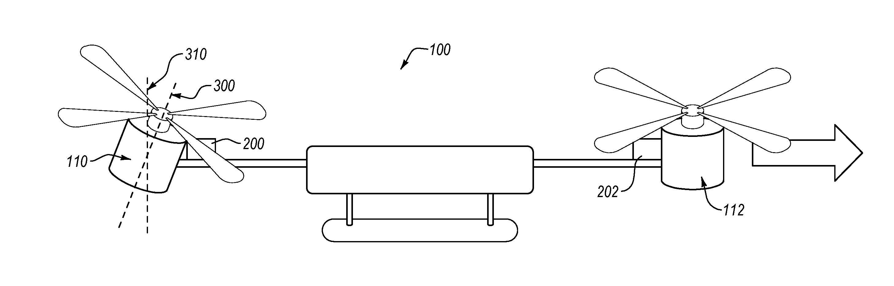
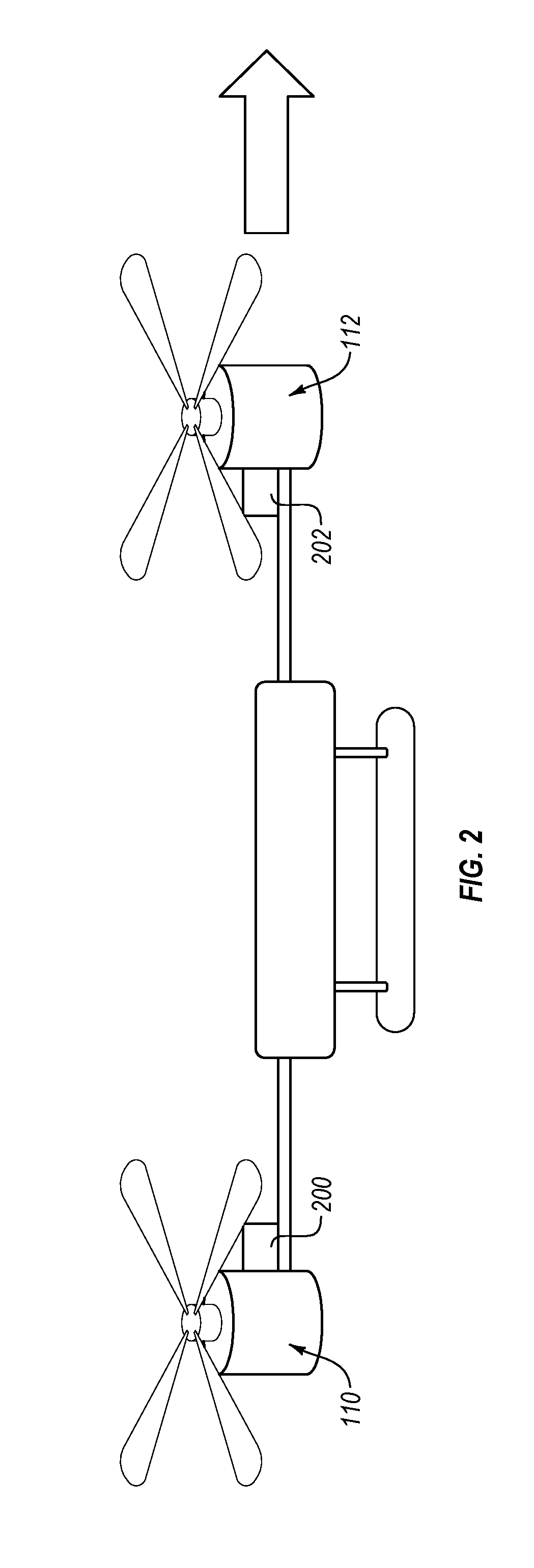
[0020]Disclosed embodiments extend to systems, methods, and apparatus configured to provide a rotor-based remote flying vehicle platform with thrust vectoring. In particular, disclosed embodiments comprise rotor-based remote flying vehicle platforms with motors that comprise at least single-axis variable tilting motors. Depending upon desired flight characteristics, the motors can be properly tilted to increase directional thrust and to minimize drag caused by the vehicle frame. As such, the range and speed of a particular rotor-based remote flying vehicle platform can be significantly incre...


PUM


Abstract

A rotor-based remote flying vehicle platform comprises a central frame with a control center that is configured to control motors mounted to the vehicle platform. A first arm is connected to the central frame and extends outward. A first motor is mounted to the first arm. The first motor is in communication with the control center. Further, a first tilt actuator is configured to tilt the first motor within a first plane.

Description

CROSS-REFERENCE TO RELATED APPLICATIONS[0001]This application claims the benefit of and priority to U.S. Provisional Patent Application Ser. No. 62 / 193,827 filed on 17 Jul. 2015 and entitled “THRUST VECTORING ON A ROTOR-BASED REMOTE VEHICLE,” which application is expressly incorporated herein by reference in its entirety.BACKGROUND[0002]After being used in military application for some time, so called “drones” have experienced a significant increase in public use and interest in recent years. The proposed uses for drones has rapidly expanded to include everything from package delivery to mapping and surveillance. The wide-ranging uses for drones has also created a wide assortment of different drone configurations and models. For example, some drones are physically better suited for travelling at high speed, while other drones are physically better suited for travelling long distances.[0003]Conventional drones typically fall within two different categories—fixed-wing drones and rotor...

Claims


Application Information

Patent Timeline
Patent Type & Authority Applications(United States)
IPC IPC(8): B64C27/52G05D1/10B64C39/02
CPCB64C27/52B64C39/024G05D1/101B64C2201/145B64C2201/027B64C2201/108B64C2201/146B64C27/08G05D1/0858B64U2201/104B64U10/10B64U10/13B64U30/20B64U50/19B64U2201/20G05D1/0808
Inventor MATUS, GEORGE MICHAEL
Owner UAVPATENT CORP
Why Eureka
Try Eureka