
Sky-dome lighting system

a technology of sky-dome and lighting system, which is applied in outdoor lighting, lighting and heating apparatus, decoration arts, etc., can solve problems such as disadvantage, affecting perception, and mirror-like facades

Inactive Publication Date: 2017-01-19
COELUX
View PDF9 Cites 16 Cited by
  • Summary
  • Abstract
  • Description
  • Claims
  • Application Information

AI Technical Summary

Benefits of technology

This patent text is trying to find ways to reduce the impact of reflected light in a scene. The text describes two methods: N 1 and N2 The first method aims to minimize the contribution of any reflected light. The second method aims to reduce the impact of any specific reflected light. These methods can be used to create useful and visually appealing images.

Problems solved by technology

Introducing a reflective feature as, for example, in WO 2015 / 172821 A1 mentioned above, however, may affect the perception due to the presence of the reflection.
On the other side, a mirror-like facade may—similar to large windows—disadvantageously not be recognized by birds flying against and impacting on the facade that is, for example, perceived as the sky.

Method used


Image

  • Sky-dome lighting system
  • Sky-dome lighting system
  • Sky-dome lighting system

Examples


Embodiment Construction

[0057]The following is a detailed description of exemplary embodiments of the present disclosure. The exemplary embodiments described therein and illustrated in the drawings are intended to teach the principles of the present disclosure, enabling those of ordinary skill in the art to implement and use the present disclosure in many different environments and for many different applications. Therefore, the exemplary embodiments are not intended to be, and should not be considered as, a limiting description of the scope of patent protection. Rather, the scope of patent protection shall be defined by the appended claims.

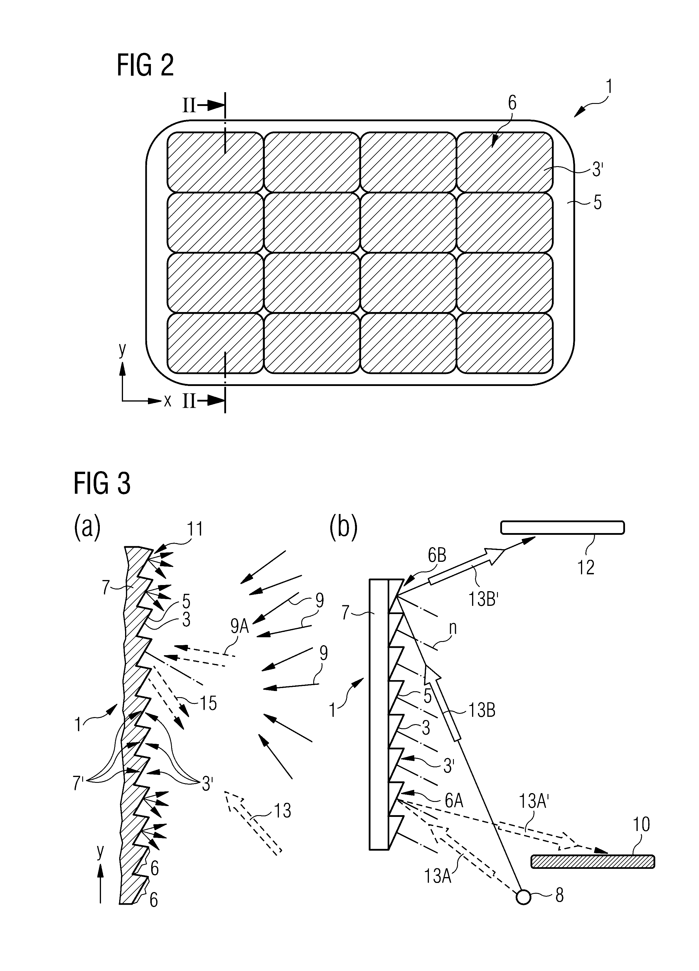
[0058]The disclosure is based in part on the realization that in systems like those described in the above mentioned WO 2015 / 172821 A1 the specular reflection of a surrounding scene, as for example a scene of a recognizable indoor or outdoor environment or any scene featuring a spatially structured luminance distribution, is superimposed as a background to the blue scat...


PUM

PropertyMeasurementUnit
sizeaaaaaaaaaa
particle diameteraaaaaaaaaa
wavelength rangeaaaaaaaaaa

Abstract

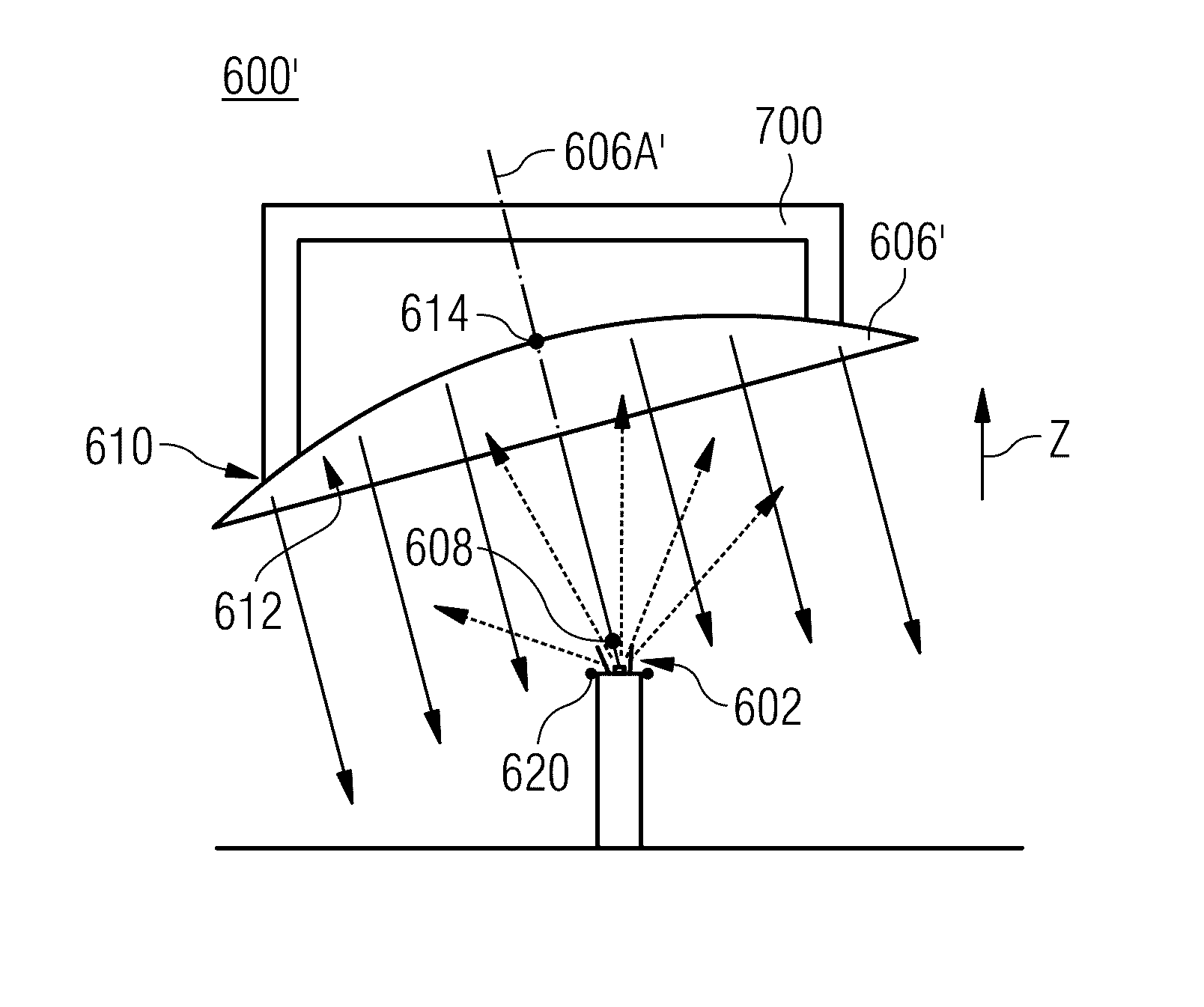
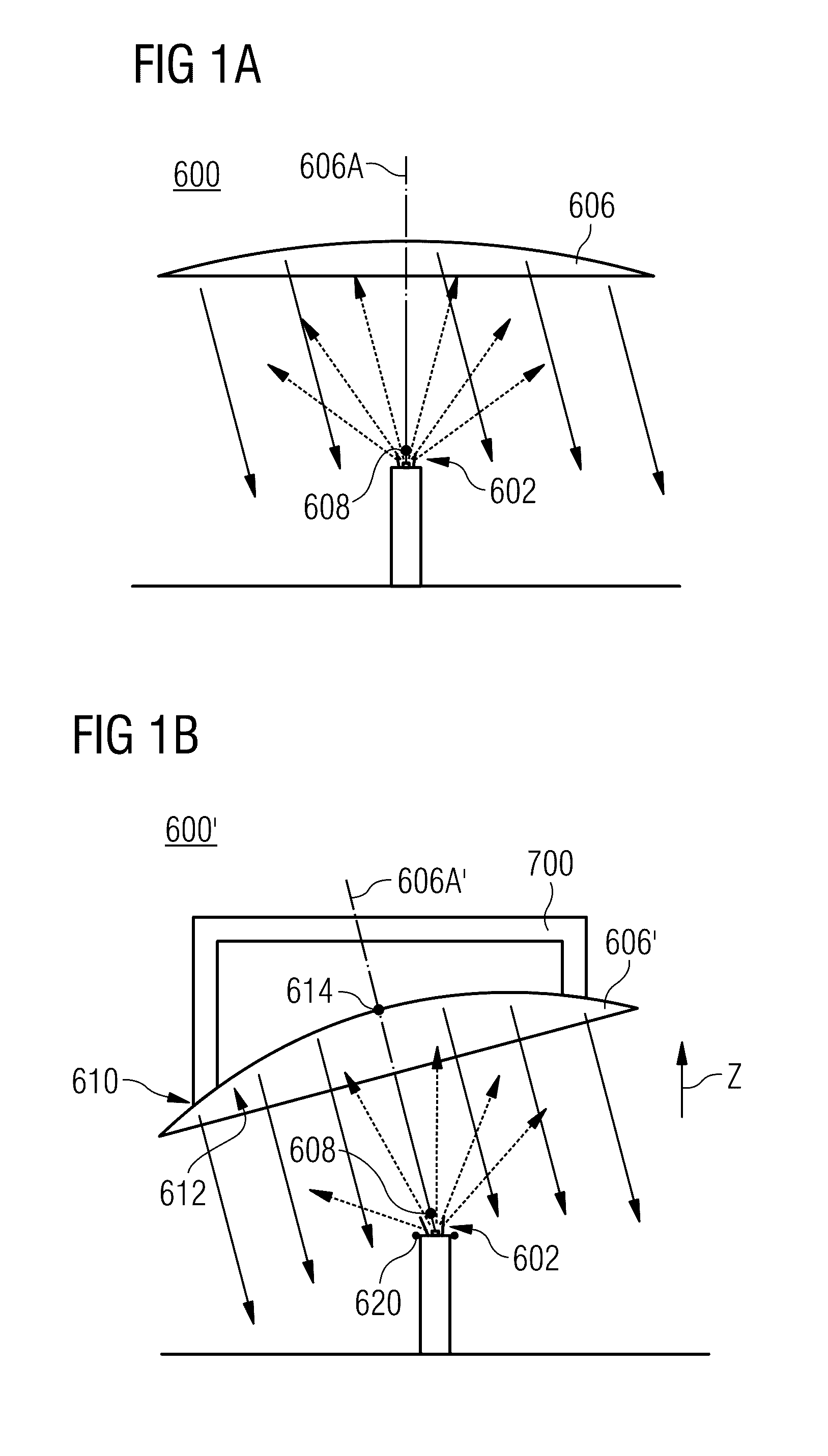
A lighting system comprises a chromatic reflective unit (606), and a light source (602), wherein the chromatic reflective unit (606) is shaped as a rotational paraboloid or a portion of a rotational paraboloid, and the light source (602) is positioned close to or at the paraboloid focal position.

Description

CROSS REFERENCE TO RELATED APPLICATIONS[0001]The present application claims priority to PCT / EP2015 / 002318 filed 19 Nov. 2015, and PCT / EP2015 / 001454 filed 15 Jul. 2015 of the same applicants. The contents of both of these applications are incorporated herein by reference in their entireties.TECHNICAL FIELD[0002]The present disclosure relates generally to chromatic mirror units and in particular to nanoparticle based light affecting units that may be applied in lighting systems or in facade structures of buildings to provide for a desired optical and visual effect.BACKGROUND[0003]The improvements in mirror manufacturing techniques during the 16th century caused an increasing use of optical mirror elements in interior architecture. For example, the overlay of a portion of a wall with a reflective surface generated the impression of space enhancement and an increase of depth perception. Since then, mirrors became essential components capable of improving the comfort of an ambience throu...

Claims


Application Information

Patent Timeline
Patent Type & Authority Applications(United States)
IPC IPC(8): F21V13/10F21V17/10F21V7/22F21V7/06
CPCF21V13/10F21V7/06F21V17/10F21W2121/004F21Y2115/10F21Y2105/10F21V7/22B32B17/1022C03C17/007C03C17/06C03C2217/445C03C2217/45C03C2217/475C03C2218/365F21V7/0008F21W2131/107G02B3/08G02B5/0231G02B5/0242G02B5/0284G02B5/0294C03C19/00
Inventor DI TRAPANI, PAOLOMAGATTI, DAVIDELOTTI, ANTONIO
Owner COELUX
Learn More