Multi-mode resonant wireless power transmitter

Active Publication Date: 2017-01-19
MEDIATEK INC
View PDF13 Cites 7 Cited by
  • Summary
  • Abstract
  • Description
  • Claims
  • Application Information

AI Technical Summary

Benefits of technology

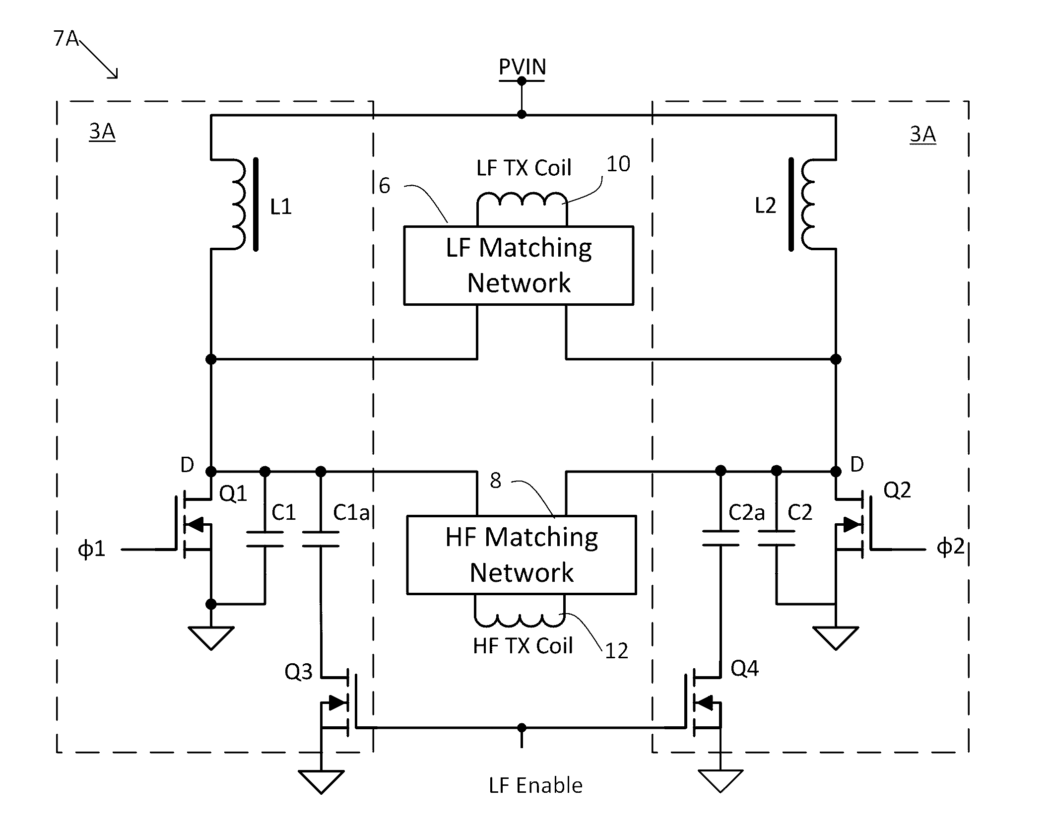
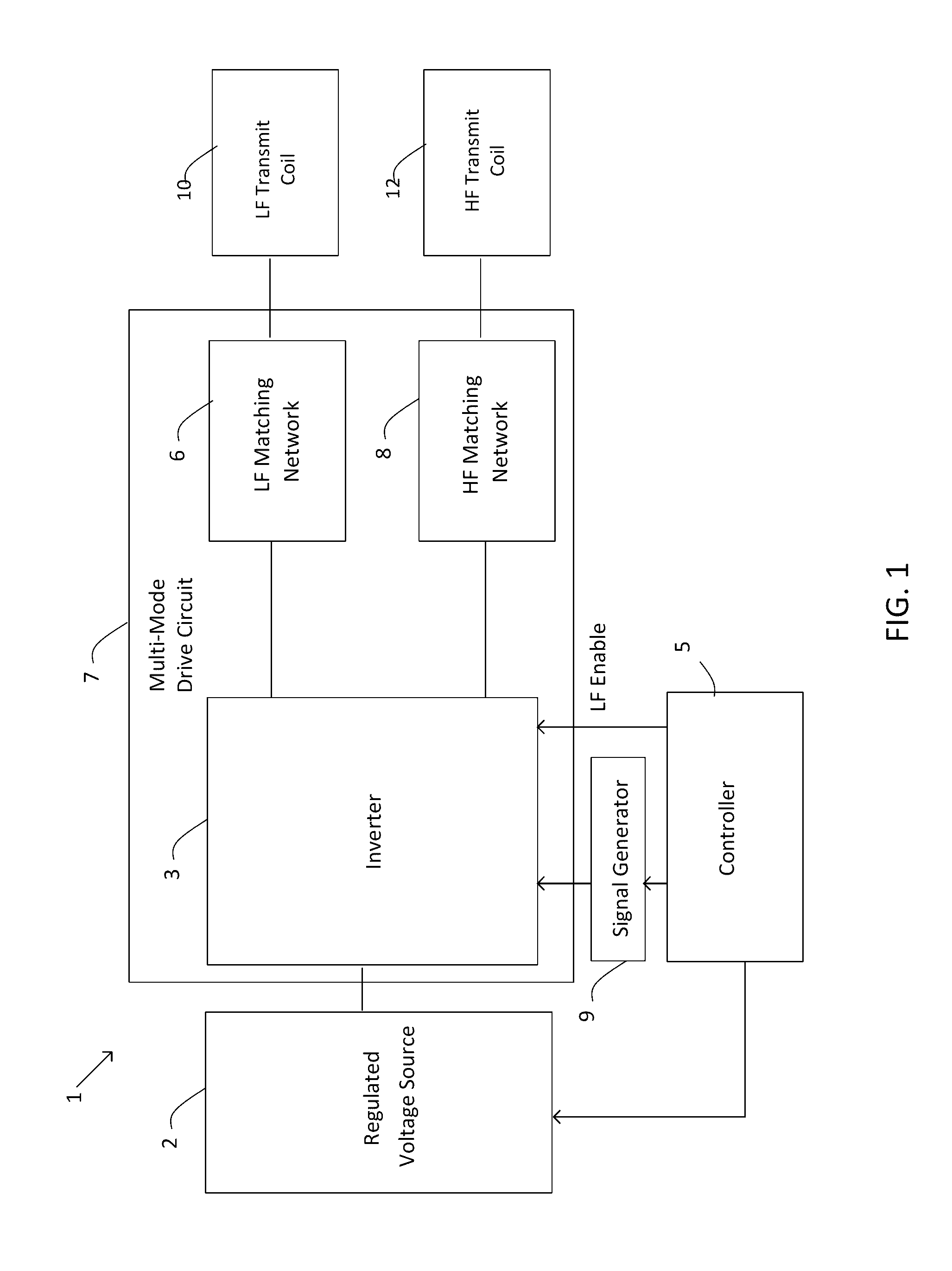
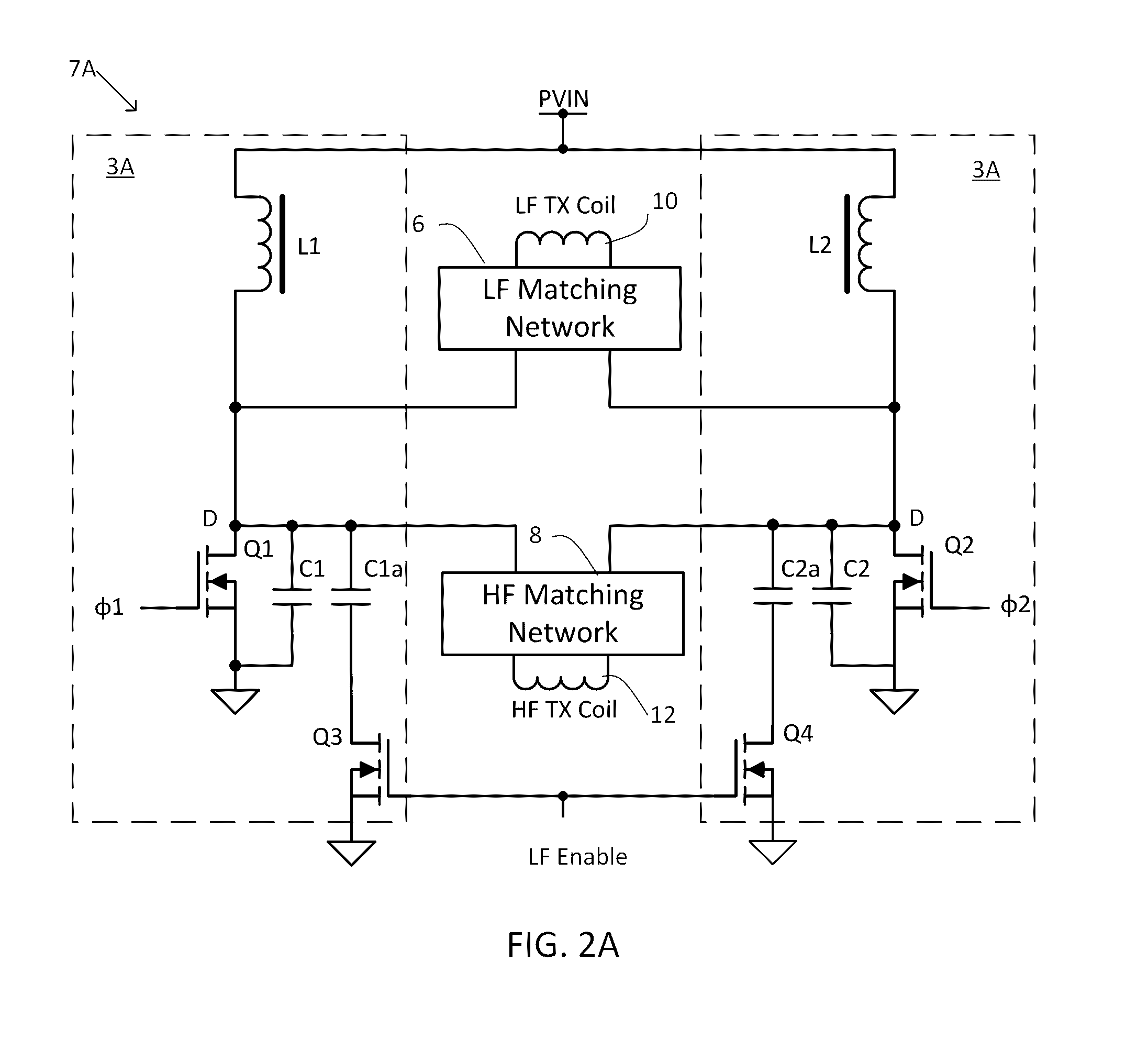
[0008]Some embodiments relate to wireless power transmitter that includes a multi-mode drive circuit having a controllable resonant frequency. The multi-mode drive circuit is controlled to have a first resonant frequency to drive wireless power transmission a

Problems solved by technology

Currently, due to the difference in operating frequency, WPTS systems of different types are not interoperable.
T

Method used


Image

  • Multi-mode resonant wireless power transmitter
  • Multi-mode resonant wireless power transmitter
  • Multi-mode resonant wireless power transmitter

Examples


Example

[0018]The inventors have recognized and appreciated that a multi-mode wireless power transmitter capable of transmitting wireless power at different frequencies can facilitate providing power to different types of wireless power receivers designed to operate at different frequencies. Such a multi-mode wireless power transmitter can allow providing power to a wider variety of electronic devices. For example, in some embodiments a multi-mode wireless power transmitter can be configured to provide power to both MI and MR receivers. In some embodiments, a multi-mode wireless power transmitter can provide power to devices that are designed according to a variety of different wireless charging specifications, such as the Qi standard promulgated by WPC, and other specifications designed for wireless power delivery at other frequencies, such as specifications for MR receivers, or other MI specifications. Such a multi-mode wireless power transmitter can support different types of receivers, ...


PUM


Abstract

A wireless power transmitter includes a multi-mode drive circuit having a controllable resonant frequency. The multi-mode drive circuit is controlled to have a first resonant frequency to drive wireless power transmission at a first transmit frequency. The multi-mode drive circuit is also controlled to have a second resonant frequency higher than the first resonant frequency to drive wireless power transmission at a second transmit frequency higher than the first transmit frequency.

Description

CROSS-REFERENCE TO RELATED APPLICATIONS[0001]This application claims priority to U.S. provisional application Ser. No. 62 / 193,803, titled “DUAL MODE CLASS-E WIRELESS POWER TRANSMITTER,” filed Jul. 17, 2015, which is hereby incorporated by reference in its entirety.BACKGROUND[0002]1. Technical Field[0003]The techniques described herein relate generally to wireless power delivery, and particularly to a wireless power transmitter capable of transmitting wireless power at more than one frequency.[0004]2. Discussion of the Related Art[0005]Wireless Power Transfer Systems (WPTS) are gaining increasing popularity as convenient way to deliver power without wires or connectors. WPTS currently under development in the industry can be separated in two major classes: magnetic induction (MI) systems and magnetic resonance (MR) systems. Both types of systems include a wireless power transmitter and a wireless power receiver. Such systems can be used to power or charge mobile devices such as smart...

Claims


Application Information

Patent Timeline
IPC IPC(8): H02J5/00
CPCH02J5/005H02J50/12H02J50/80H02J50/402
Inventor MURATOV, VLADIMIR A.
Owner MEDIATEK INC
Why Eureka
Try Eureka