Miniature projection scanning system

A scanning system and micro-projection technology, applied in the field of micro-projection scanning system, to achieve the effects of high resolution and large field of view display, simple structure, high resonance frequency and reliability

Pending Publication Date: 2020-02-18
成都英飞睿技术有限公司
View PDF0 Cites 1 Cited by
  • Summary
  • Abstract
  • Description
  • Claims
  • Application Information

AI Technical Summary

Problems solved by technology

Therefore, the high-resolution display restricts the mechanical half-angle of the horizontal scanning mirror

Method used


Image

  • Miniature projection scanning system
  • Miniature projection scanning system
  • Miniature projection scanning system

Examples


Embodiment Construction

[0031] The following will clearly and completely describe the technical solutions in the embodiments of the present invention with reference to the accompanying drawings in the embodiments of the present invention. Obviously, the described embodiments are only some, not all, embodiments of the present invention. Based on the embodiments of the present invention, all other embodiments obtained by persons of ordinary skill in the art without making creative efforts belong to the protection scope of the present invention.

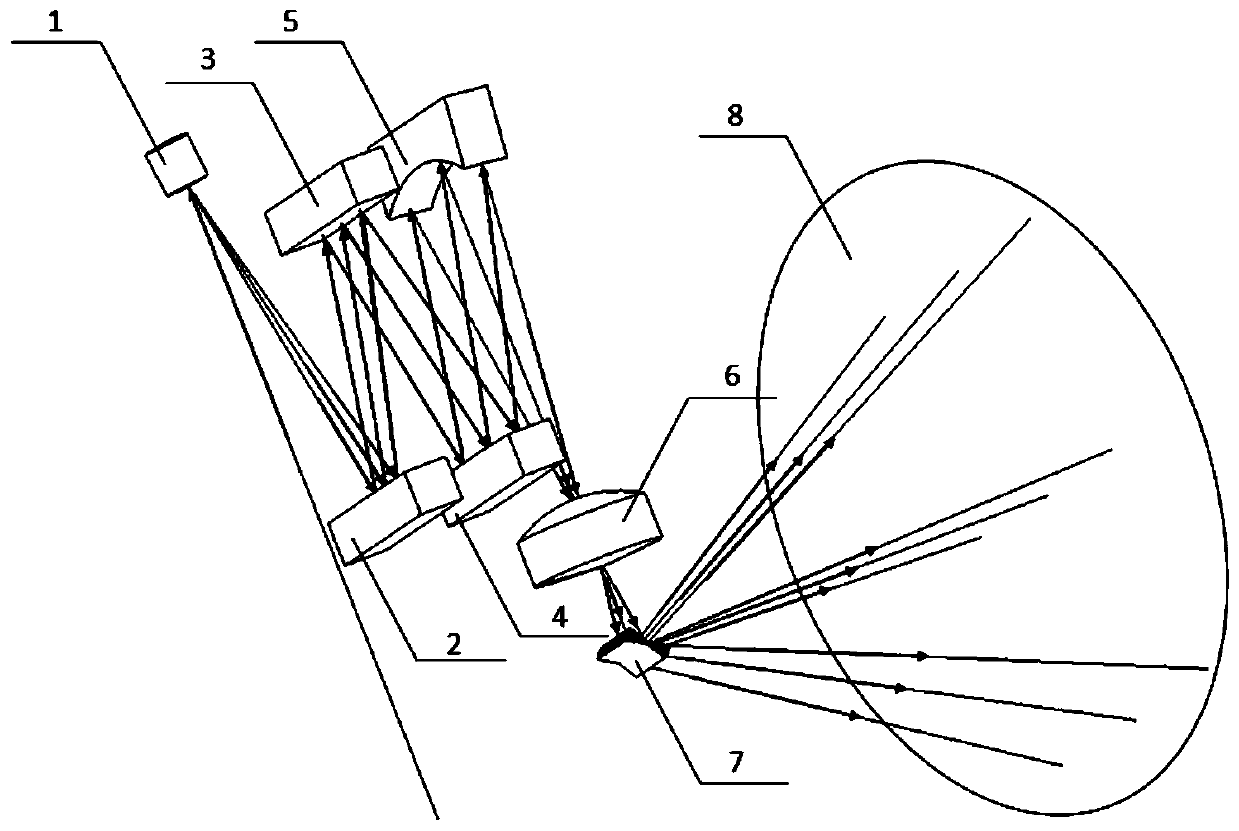
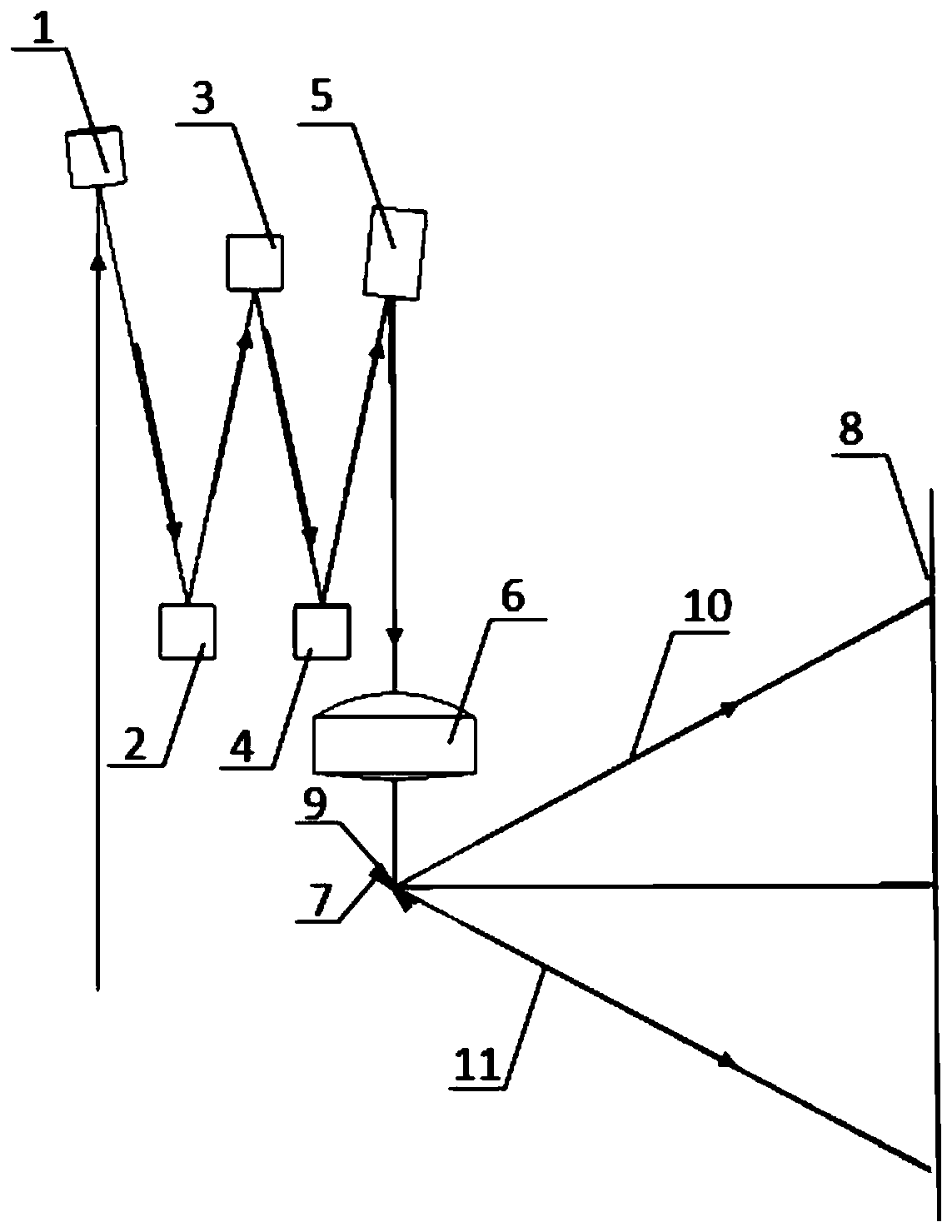
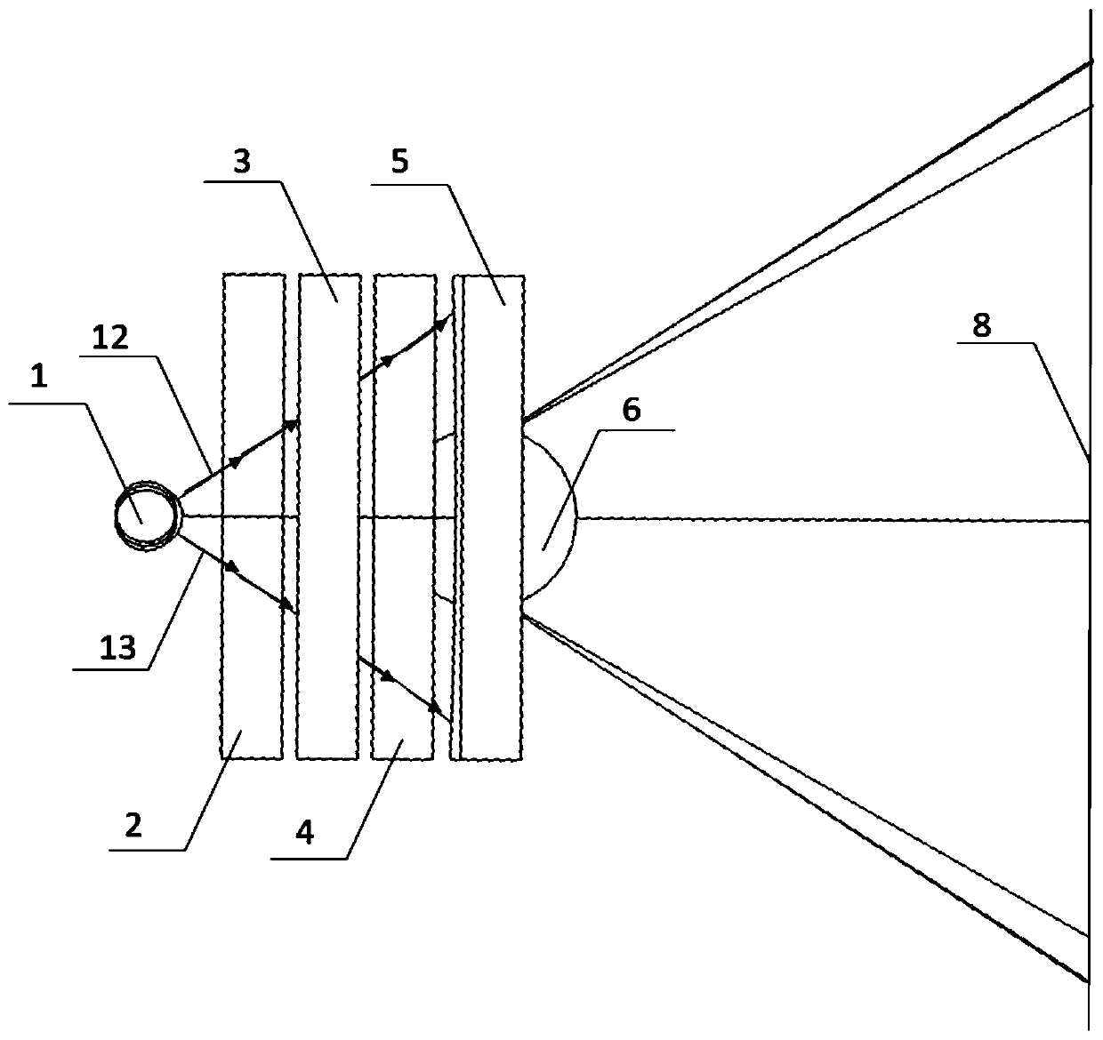
[0032] The invention provides a micro-projection scanning system, such as Figure 1 to Figure 3 As shown, it includes: the first MEMS scanning mirror (the first micro-vibrating mirror) 1, the relay reflection device (including the first mirror 2, the second mirror 3, the third mirror 4 and the fourth mirror 5), Collimator lens 6, the second MEMS scanning mirror (second micro vibrating mirror) 7 (or 9), projection screen 8; Wherein,

[0033] The first MEMS sca...


PUM


Abstract

The application discloses a miniature projection scanning system which comprises a first MEMS scanning mirror, a relay reflection device, a collimating lens, a second MEMS scanning mirror and a projection screen. A laser beam is subjected to first-scanning-angle resonance motion one-dimensional scanning in a horizontal direction through the first MEMS scanning mirror; after the laser beam is reflected by the relay reflection device multiple times, the view field of the first MEMS scanning mirror in the horizontal direction is expanded and folded; the collimating lens collimates the laser beamafter multi-times reflection and controls the size of a pixel point; and then second-scanning-angle quasi-static motion and another-dimensional scanning are carries out on the laser beam in a verticaldirection by the second MEMS scanning mirror and the processed light beam is irradiated on the projection screen. The maximum value of the first scanning angle is smaller than the maximum value of the second scanning angle. With the miniature projection scanning system having a simple structure, two-dimensional image scanning as well as high-resolution and large-field-angle display can be realized.

Description

technical field [0001] The invention relates to the field of micro-projection technology, in particular to a micro-projection scanning system. Background technique [0002] Laser micro-projection is mainly used in smart car screen head-up displays, AR, VR and other wearable devices, smart phones, digital cameras, various consumer electronics products, artificial intelligence and biomedicine and other fields. [0003] Most of the existing miniature projections on the market are area array spatial light modulation projection displays, such as liquid crystal display (LCD), digital light processing (DLP), liquid crystal on silicon (LCoS), and their resolution and field of view are controlled by spatial light. The number of physical units of the modulator determines that to achieve a large field of view needs to increase the size, weight and power consumption of the projection device, and the light utilization rate is not high. It is very difficult to realize the reduction of pi...

Claims


Application Information

Patent Timeline
Patent Type & Authority Applications(China)
IPC IPC(8): G02B26/08G02B26/10
CPCG02B26/0833G02B26/101
Inventor 徐丹慧方国明黄印向思桦
Owner 成都英飞睿技术有限公司
Why Eureka
Try Eureka