Display device and transmission processing method for image data signal

a transmission processing and image data technology, applied in the field of display devices and transmission processing methods of image data signals, can solve the problems of increasing power consumption associated with increasing transmission frequency, increasing transmission frequency, electro-magnetic interference, etc., and achieves the effects of increasing the transmission frequency of image data, high display quality, and reducing power consumption

Active Publication Date: 2016-02-25
LAPIS SEMICON CO LTD
View PDF3 Cites 5 Cited by
  • Summary
  • Abstract
  • Description
  • Claims
  • Application Information

AI Technical Summary

Benefits of technology

[0011]Thus, even when an error is generated in the image data received at the driver due to the EMI caused by an increase in the transmission frequency of the image data in the display device, an image with high display quality can be displayed since such an error is corrected.
[0012]If all pixels for one horizontal scanning line have the identical color, no error correction process as described above is performed. Instead, the representative pixel data pieces contained in the transmission image data signal is converted to pixel driving voltages and these voltages are applied to the display panel. Thus, at this time, a power consumption can be reduced by an amount necessary to perform the error correction process.
[0013]Thus, according to the present invention, a deterioration in display quality associated with an increase in the transmission frequency of image data in the display device and an increase in power consumption can be suppressed.

Problems solved by technology

Thus, there is concern about an increase in power consumption associated with an increase in the transmission frequency.
However, there is a risk of causing electro-magnetic interference, what is called EMI, along with an increase in the transmission frequency of image data in the display device and thus generating an error in the image data received at the driver.
This deteriorates the display quality of the image.

Method used


Image

  • Display device and transmission processing method for image data signal
  • Display device and transmission processing method for image data signal
  • Display device and transmission processing method for image data signal

Examples


Embodiment Construction

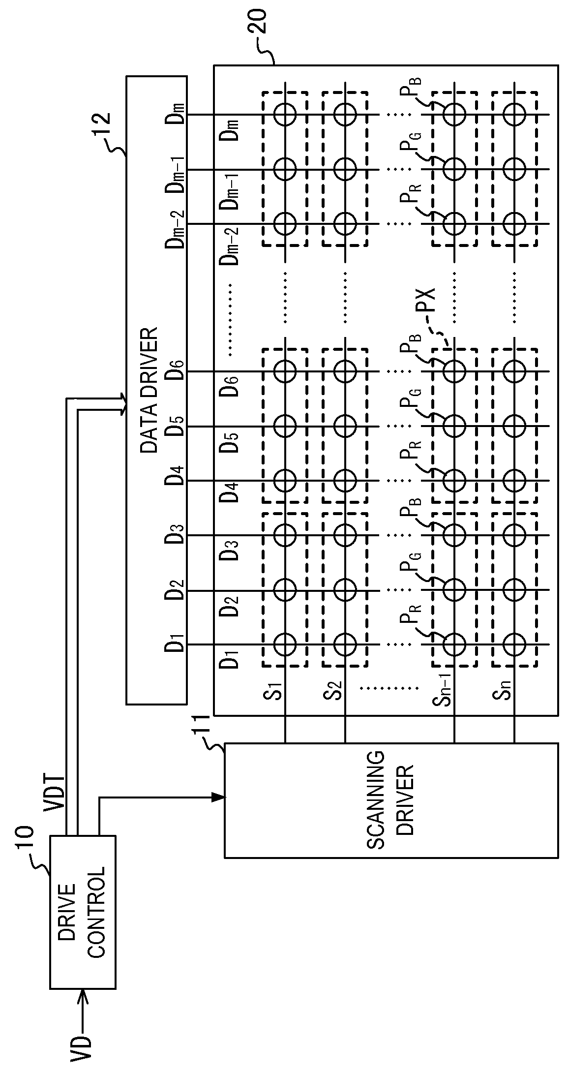
[0023]FIG. 1 is a diagram illustrating a general configuration of a display device according to the present invention.

[0024]In FIG. 1, a display panel 20 as a liquid crystal panel, for example, includes: a liquid crystal layer (not shown); “n” (n is an integer larger than or equal to 2) horizontal scanning lines S1 to Sn extending in a horizontal direction of a two-dimensional screen; and “m” (m is an integer larger than or equal to 2) data lines D1 to Dm extending in a vertical direction of the two-dimensional screen. A red display cell PR for red display, a green display cell PG for green display, or a blue display cell PB for blue display is formed at an intersection between one horizontal scanning line and one data line. More specifically, among the data lines D1 to Dm, the red display cells PR are formed in the (3·t−2)th data lines (t is a natural number), i.e., D1, D4, D7, . . . , and Dm-2. Among the data lines D1 to Dm, the green display cells PG are formed in the (3·t−1)th d...


PUM


Abstract

A transmission image data signal including: a coded data block obtained by performing an error correction coding on a sequence of pixel data pieces in input image data; and a representative pixel data pieces group containing three pixel data pieces corresponding to red, green, and blue, respectively, in the sequence of the pixel data pieces is transmitted to a driver in a display panel. The driver converts the sequence of the pixel data pieces obtained by performing an error correction on the transmission image data signal to pixel driving voltages and applies these voltages to the display panel. If pixels for one horizontal scanning line have an identical color, the driver performs no error correction. Instead, the driver converts the representative pixel data pieces group to pixel driving voltages and applies these voltages to the display panel.

Description

BACKGROUND OF THE INVENTION[0001]1. Field of the Invention[0002]The present invention relates to a display device and a transmission processing method for an image data signal in the display device.[0003]2. Related Art[0004]Liquid crystal display devices as display devices each include, in addition to a liquid crystal display panel, a plurality of data drivers for driving the liquid crystal display panel and a control unit for transmitting image data to the respective drivers. In recent years, liquid crystal display panels have had increasingly higher resolution in order to display increasingly higher definition images. The transmission frequency of image data in such a liquid crystal display device has been increasing accordingly. Thus, there is concern about an increase in power consumption associated with an increase in the transmission frequency.[0005]In view of this, a data driver that achieves a lower power consumption by, when display line data of adjacent display lines are i...

Claims


Application Information

Patent Timeline
Patent Type & Authority Applications(United States)
IPC IPC(8): G09G3/20G09G3/36
CPCG09G3/2003G09G2330/021G09G3/3696G09G3/3648
Inventor KONDO, HIRONORI
Owner LAPIS SEMICON CO LTD
Why Eureka
Try Eureka