Machining device

a technology of machining device and cutting device, which is applied in the direction of metal sawing device, manufacturing tools, metal-working machine components, etc., can solve the problems of increasing the manufacturing cost of cutting device, generating unpleasant sound, noise or abnormal sound, etc., and preventing accidental or unintentional unlocking of the door. , the effect of improving the functionality of the locking devi

Active Publication Date: 2017-01-26
MAKITA CORP
View PDF4 Cites 10 Cited by
  • Summary
  • Abstract
  • Description
  • Claims
  • Application Information

AI Technical Summary

Benefits of technology

[0015]In this way, for unlocking the door, the operation member is necessary to be moved in the second direction after being rotated. Therefore, it may b

Problems solved by technology

This arrangement may lead to an increase in a manufacturing cost of the cutting device.
Also for these machining devices, there has been a problem of generation of unpleasant sound, such as sound of “pea.” It has been considered that such noise or abnormal sound may be generated when the frequency of air vibration generated by the rotation of the blade at a specific rotational speed within the cover becomes to a

Method used


Image

  • Machining device
  • Machining device
  • Machining device

Examples


Embodiment Construction

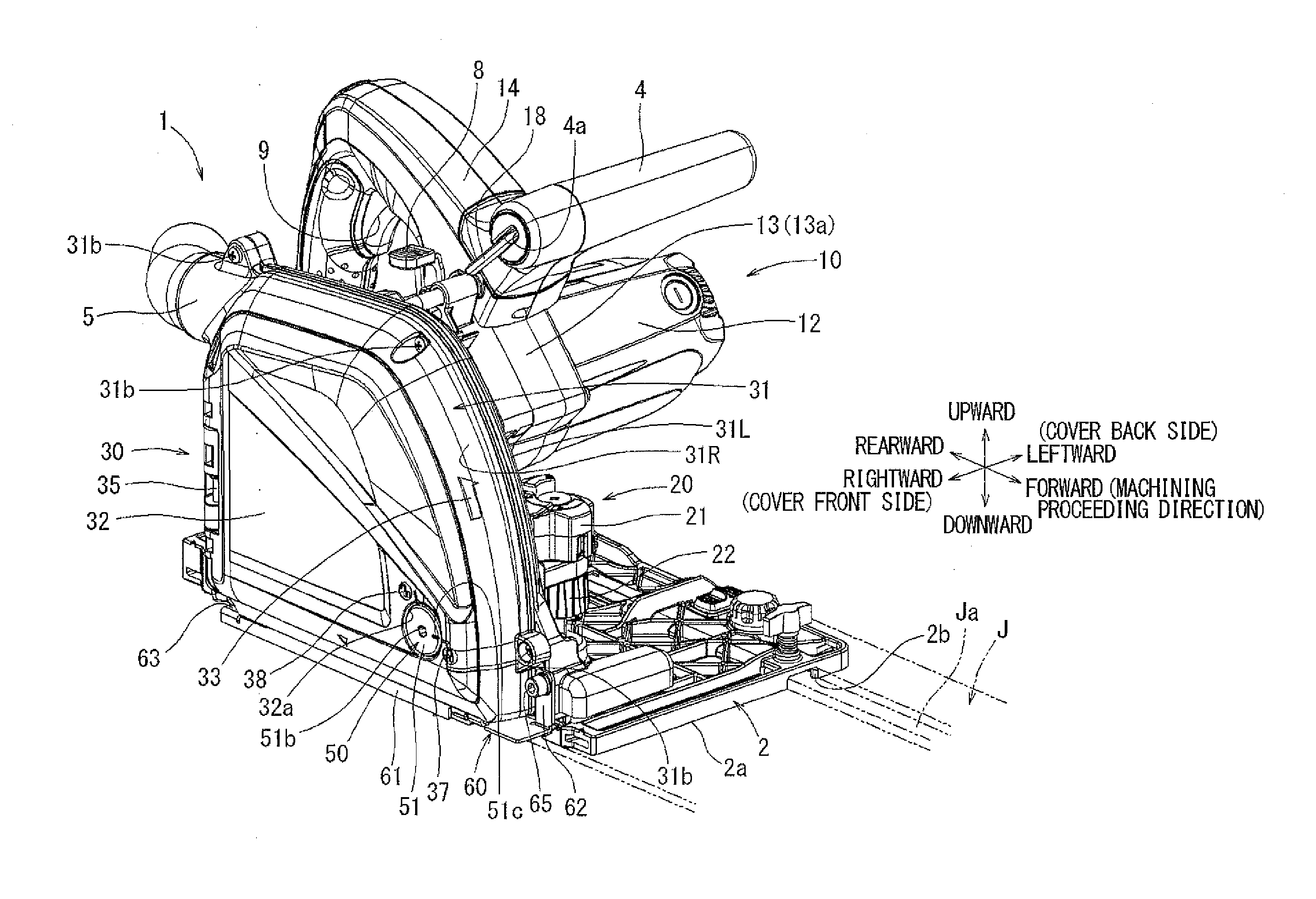
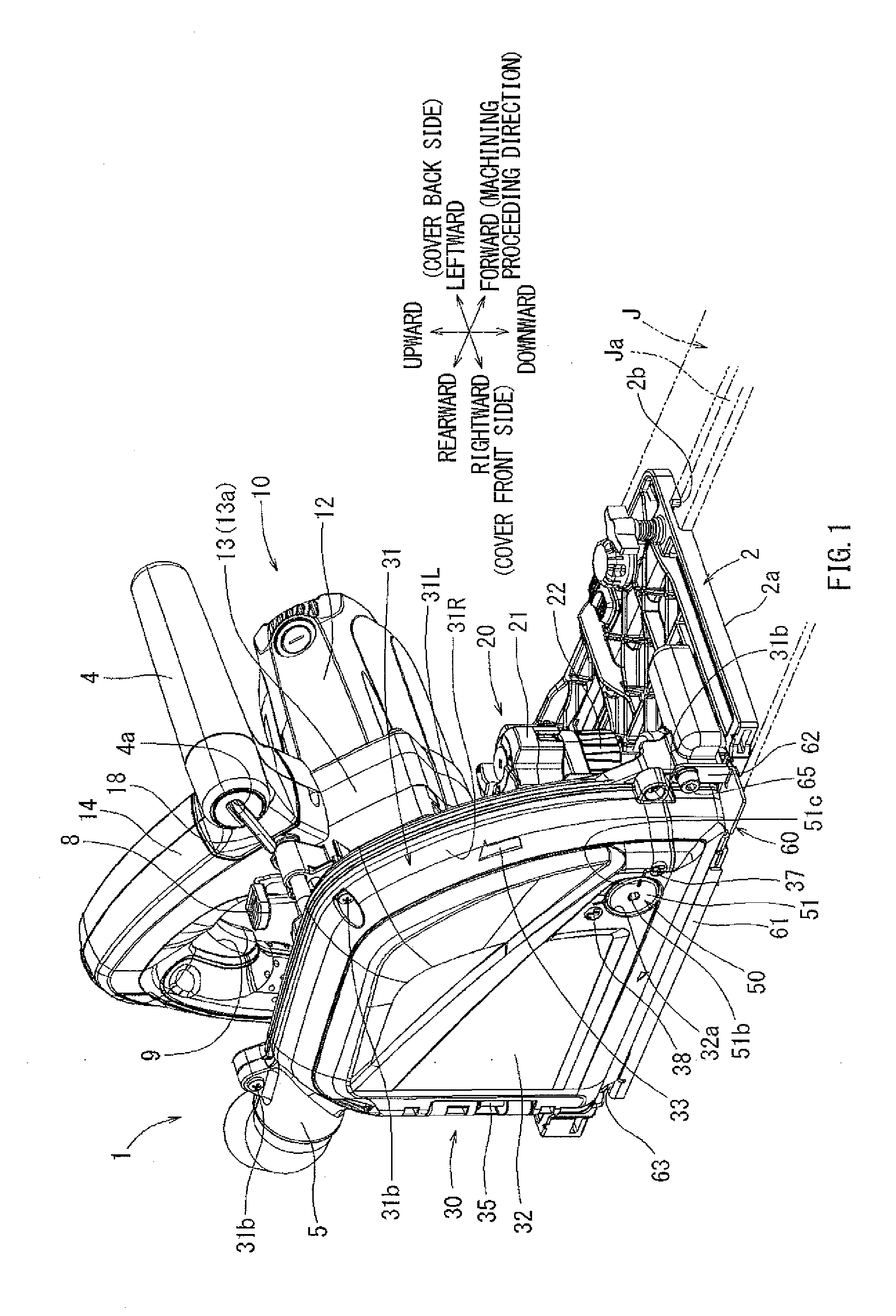
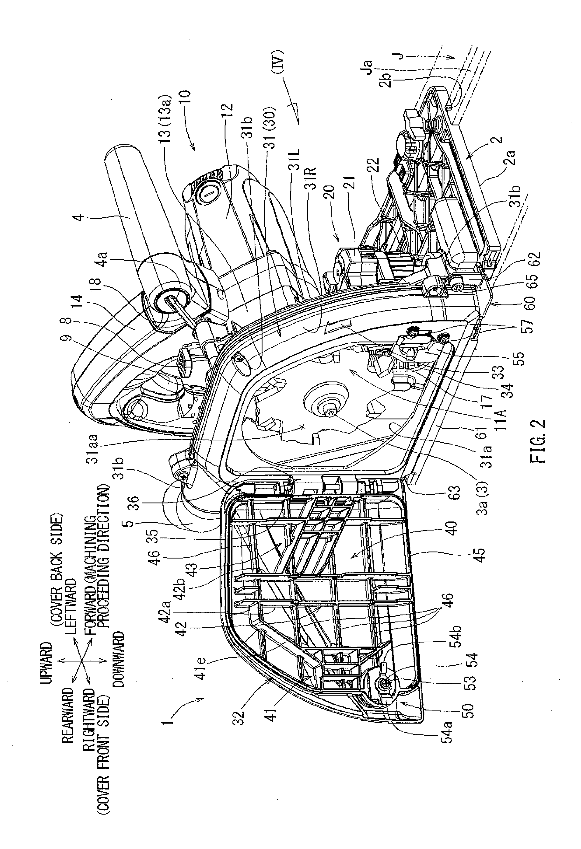
[0030]A machining device according to a representative embodiment will now be described with reference to the drawings. In the following description, with regard to forward and rearward directions for members and constructions of the machining device, a direction in which the machining device moves for performing a machining operation (hereinafter called a “machining proceeding direction”) may be determined as the forward direction. Leftward and rightward directions may be determined with reference to a position where a user is positioned for operating the machining device. Further, in the following description, the left side with respect to a blade cover will be also called as a “cover back side”, and the right side with respect to the blade cover will be also called as a “cover front side.” In this representative embodiment, a machining device 1 may be configured as a hand-held groove cutter that may have a relatively small size to be held by a hand(s) of the user and may be used ...


PUM

PropertyMeasurementUnit
Heightaaaaaaaaaa

Abstract

A machining device may include an electric motor, a blade rotatably driven by the electric motor for machining a workpiece, and a blade cover configured to surround the blade. A resonance sound reduction device may be disposed at the blade cover and may reduce air vibration generated by the rotation of the blade.

Description

CROSS-REFERENCE TO RELATED APPLICATIONS[0001]This application is based upon and claims priority to Japanese Patent Application Serial No. 2015-144321 filed on Jul. 21, 2016, the contents of which are incorporated in their entirety herein by reference.BACKGROUND[0002]Technical Field[0003]The invention generally relate to a machining device, such as a cutting device that may include a circular blade rotatably driven for performing a cutting operation or a grooving operation of a workpiece, such as an aluminum workpiece, by a predetermined depth.[0004]Related Art[0005]Japanese Laid-Open Patent Publication No. 2000-073310 (JP-A-2000-073310) discloses a technique for reducing noise that may be generated by the rotation of a blade of a cutting device that may be used for cutting a concrete floor surface and an asphalt road surface.[0006]However, in a structure for covering the blade disclosed in the above publication, a polyurethane resin material is disposed in a sound adsorbing space fo...

Claims


Application Information

Patent Timeline
IPC IPC(8): B23Q11/00B23D45/02B23Q11/06
CPCB23Q11/0096B23D45/021B23Q11/06B23D47/005B27B9/00B64F5/60
Inventor HIROSHIMA, TORUKAWAI, YUTAKUME, SHONOSE, KENJIWADA, YUKIOZAWA, NAOKI
Owner MAKITA CORP
Why Eureka
Try Eureka