Auxiliary drum drive assembly for milling machine

Active Publication Date: 2020-04-23
ROADTEC
View PDF0 Cites 0 Cited by
  • Summary
  • Abstract
  • Description
  • Claims
  • Application Information

AI Technical Summary

Benefits of technology

The invention provides an assembly for disengaging the primary drive assembly from the cutter drum in order to prevent accidental, inadvertent or uncontrolled rotation of the drum by the primary drive assembly and to allow for inspection and replacement of drum components with the primary drive assembly disengaged. It also allows for safe movement of the cutter drum by an auxiliary drum drive assembly that is independent of the primary drum drive assembly. Additionally, it allows for rotation of the cutter drum through a small angle of rotation without having to overcome the large frictional forces inherent in the primary drive assembly. The invention is adaptable to cutter drums that extend substantially across the width of the drum housing, as well as on VCS cutter drums. It provides an auxiliary drum drive assembly that can be used with cutter drums that were previously limited to use with a different auxiliary drum drive assembly. The term "milling machine" refers to a vehicle having a cutter drum that is adapted to be rotated so as to cut into the surface on which the vehicle is operated.

Problems solved by technology

Without prior surface treatment, however, this method of repair generally results in the application of insufficient quantities of paving material in the rutted, potholed or otherwise damaged areas, because the overlay will be applied at the same rate per unit of roadway width in damaged areas (which have a greater depth across the width) as in the undamaged areas.
The application of an overlay over the previously damaged areas will lead to renewed rutting or other wear damage in the new pavement in relatively short order.
This can require the raising of road shoulders, guardrails and manhole covers and the adjustment of overpass clearances, all of which will be unnecessary if a proper milling technique is employed.
The cutting teeth on the cutter drum of a milling machine are subjected to significant wear forces as the milling, reclaiming, stabilizing or recycling process is carried out.
These cutting teeth will break or become dull with use and must be periodically replaced.
However, it is hazardous for maintenance personnel to get close enough to the cutter drum for inspection while the primary drum drive assembly for the milling machine is operating, or while the cutter drum is being rotated at any significant speed, because of the risk of injury due to proximity to the rotating cutter drum.
Attempts to “bump” the rotation circuit of the primary drum drive assembly at engine idle speed in order to facilitate inspection may result in over-rotation that is not useful for inspection or uncontrolled rotation of the cutter drum that can ensnare the clothing of maintenance personnel on the cutting teeth within the drum housing.
Attempts have been made to rotate the cutter drum by hand with the power supply to the primary drive assembly of the cutter drum turned off, but the belt drive assembly, gearbox and other components of the typical primary drive assembly produce large frictional forces which must be overcome.
Furthermore, the cutter drum of a milling machine is massive and heavy, and it requires considerable torque to move it.

Method used


Image

  • Auxiliary drum drive assembly for milling machine
  • Auxiliary drum drive assembly for milling machine
  • Auxiliary drum drive assembly for milling machine

Examples


first embodiment

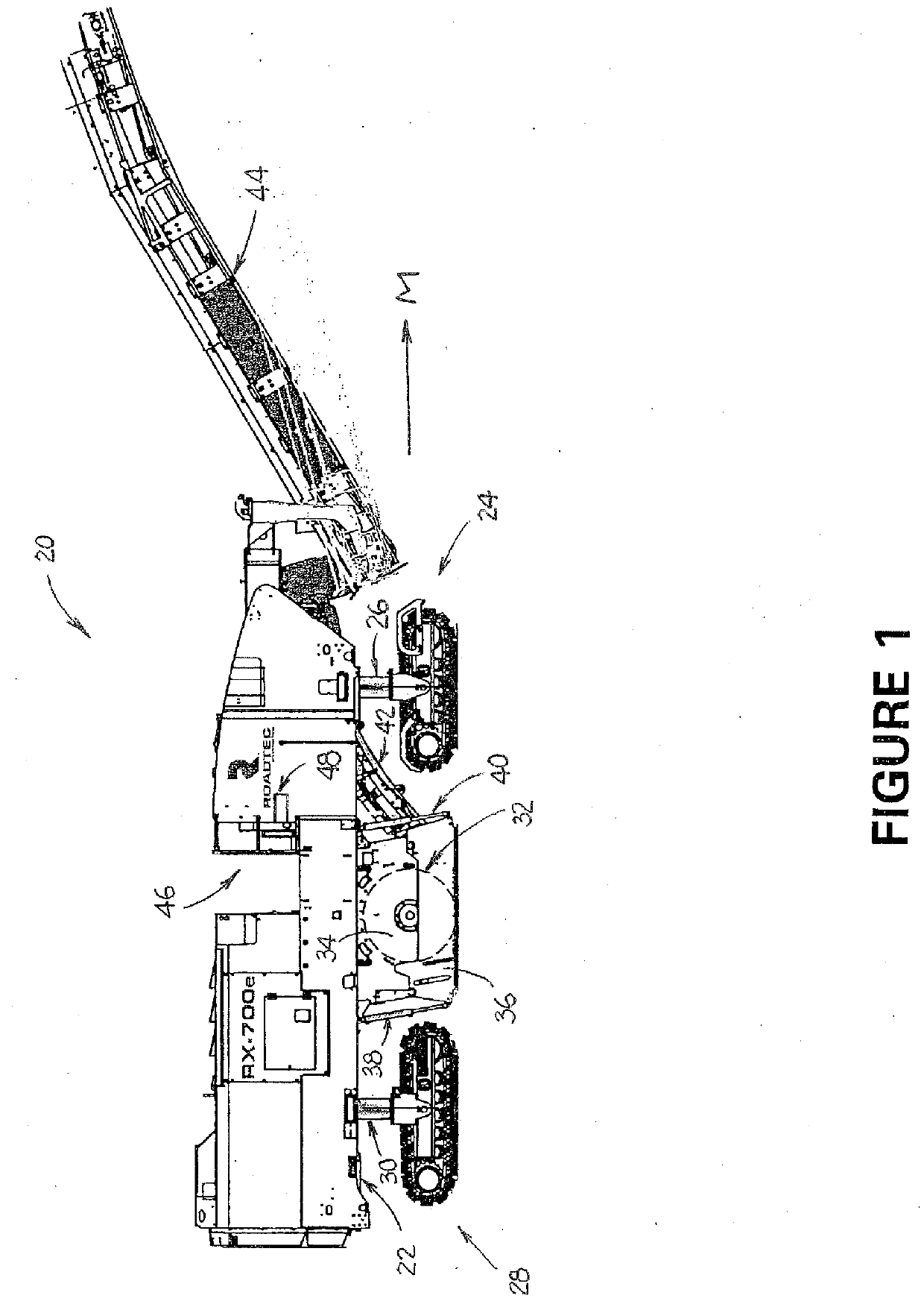
[0049]FIGS. 9-12 illustrate components of a milling machine that is substantially similar to machine 20 and includes an auxiliary drive assembly. As shown therein, cutter drum 90 is mounted for rotation on the frame of the milling machine by action of a conventional primary drum drive assembly (not shown) that includes sheave 92 which is mounted on input drive shaft 93 for cutter drum 90. The cutter drum is mounted so as to rotate within a drum housing including a first sidewall comprising upper right side plate 94 which cooperates with a lower right side plate (not shown but substantially similar to lower right side plate 36 of milling machine 20). The upper right side plate 94 is fixed to the frame (not shown), and the lower right side plate is adapted to move upwardly and downwardly with respect to the upper right side plate by the action of a pair of linear actuators (not shown but substantially similar to linear actuators 38 and 40 of milling machine 20).

[0050]The first embodim...

second embodiment

[0052]FIG. 13 illustrates the auxiliary drum drive assembly. This embodiment is particularly useful in connection with cutter drum 290 that includes a cutter assembly 292 that does not extend substantially across width “W” of the drum housing, between first sidewall 294 and second sidewall 296, leaving an open section 298 on the side of the drum housing adjacent to first sidewall 294.

[0053]As shown in FIG. 13, input drive shaft 300 is mounted through first sidewall 294 of the drum housing and includes first auxiliary pulley 306 that is mounted inside the drum housing. Auxiliary drive motor 308 is mounted through first sidewall 294 and includes auxiliary drive motor shaft 310 and second auxiliary pulley 312 that is mounted on auxiliary drive motor shaft 310 inside the drum housing. Auxiliary drive motor 308 is essentially the same as auxiliary drive motor 96 except that first auxiliary pulley 306 is mounted on the auxiliary drive motor instead of drive wheel 100. Auxiliary drive moto...


PUM


Abstract

A milling machine for milling a surface of a roadway includes a frame and a milling assembly having a cutter drum that is mounted for rotation with respect to the frame. The cutter drum has a drive shaft on which a sheave is mounted. A primary drum drive assembly is adapted to rotate the cutter drum with respect to the frame. The primary drum drive assembly includes a drive belt that cooperates with the sheave on an input drive shaft for the cutter drum to rotate the cutter drum. A belt lift assembly may be operated to selectively disengage the drive belt from the sheave of the input drive shaft for the cutter drum, so that an auxiliary drum drive assembly comprising an auxiliary drive motor may be operated to rotate the cutter drum independently of the primary drum drive assembly.

Description

CROSS-REFERENCE TO RELATED APPLICATION[0001]This application claims the benefit of co-pending U.S. patent application Ser. No. 16 / 038,871 which was filed on Jul. 18, 2018 and which claims the benefit of U.S. Provisional Patent Application No. 62 / 535,320 which was filed on Jul. 21, 2017.FIELD OF THE INVENTION[0002]This invention relates generally to an auxiliary drum drive assembly for the cutter drum of a milling machine that operates independently of the primary drum drive assembly and is adapted to move the cutter drum through a small angle of rotation at a low rotational speed. The invention also includes an assembly for disengaging the drive belt of the primary drum drive assembly from the cutter drum of a milling machine in order to facilitate the operation of the auxiliary drum drive assembly.BACKGROUND OF THE INVENTION[0003]Roadway repair is often accomplished by overlaying the existing pavement (whether of concrete or asphalt composition) with a new layer (often called a lev...

Claims


Application Information

Patent Timeline
IPC IPC(8): E01C23/088E01C23/12
CPCE01C23/127E01C23/088F16H7/0827
Inventor AVANS, TODDBEVILL, JAMES H.
Owner ROADTEC
Why Eureka
Try Eureka