Coupling device, wing assembly for an aircraft comprising such coupling device and aircraft comprising such wing assembly

a technology of coupling device and wing assembly, which is applied in the direction of aircraft transmission means, wing adjustment, aircraft power plants, etc., can solve the problems of large wing span, and achieve the effect of non-linear capabilities of coupling device, instant relief of load acting on the wing, and fast movemen

Active Publication Date: 2017-01-26
AIRBUS DEFENCE & SPACE +1
View PDF5 Cites 22 Cited by
  • Summary
  • Abstract
  • Description
  • Claims
  • Application Information

AI Technical Summary

Benefits of technology

[0023]An advantage of the invention is that the coupling device allows a sufficiently fast movement of the second wing section with regard to the first wing section in order to allow an almost instant alleviation of the load acting on the wing.
[0024]The coupling device may be arranged instead of a mechanical spring and in particular instead of a non-linear spring that is arranged between the first wing section and the second wing section according to the prior art. An advantage of the coupling device is that the non-linear capabilities of the coupling device may be achieved in a simpler fashion compared to a mechanical spring. Furthermore, the coupling device may have a reduced likelihood of fatigue failure compared to a mechanical spring.
[0025]It is preferred that the coupling device further comprises a first throttle element arranged in the first fluid pathway.
[0026]The first throttle element may constituted by a throttle and / or a restriction in the first fluid pathway. The first throttle element may change the orifice of the first fluid pathway. The first throttle element affects the damping capabilities of the coupling device. Hence, the first throttle element may be designed such that the damping of the coupling device is adapted to the configurations of the first wing section and the second wing section.
[0027]The first throttle element may be used to adjust the velocity with which the first wing section (or first component) may rotate (move) relative to the second wing section (or second component) once the first pressure relief valve opens. The effect of the first throttle element depends on the fluid resistance of the first throttle element and on the distance between the first throttle element and the first pressure relief valve.
[0028]The first throttle element can be configured such that the fluid resistance can be varied remotely. For example, the first throttle element is configured such that the diameter of the orifice of the first throttle element can be varied.

Problems solved by technology

Possible issues arising with very large wing spans may be associated with the structure of the wings as they become very heavy in order to be able to carry the wing bending loads caused by maneuvers and gusts.

Method used


Image

  • Coupling device, wing assembly for an aircraft comprising such coupling device and aircraft comprising such wing assembly
  • Coupling device, wing assembly for an aircraft comprising such coupling device and aircraft comprising such wing assembly
  • Coupling device, wing assembly for an aircraft comprising such coupling device and aircraft comprising such wing assembly

Examples


Embodiment Construction

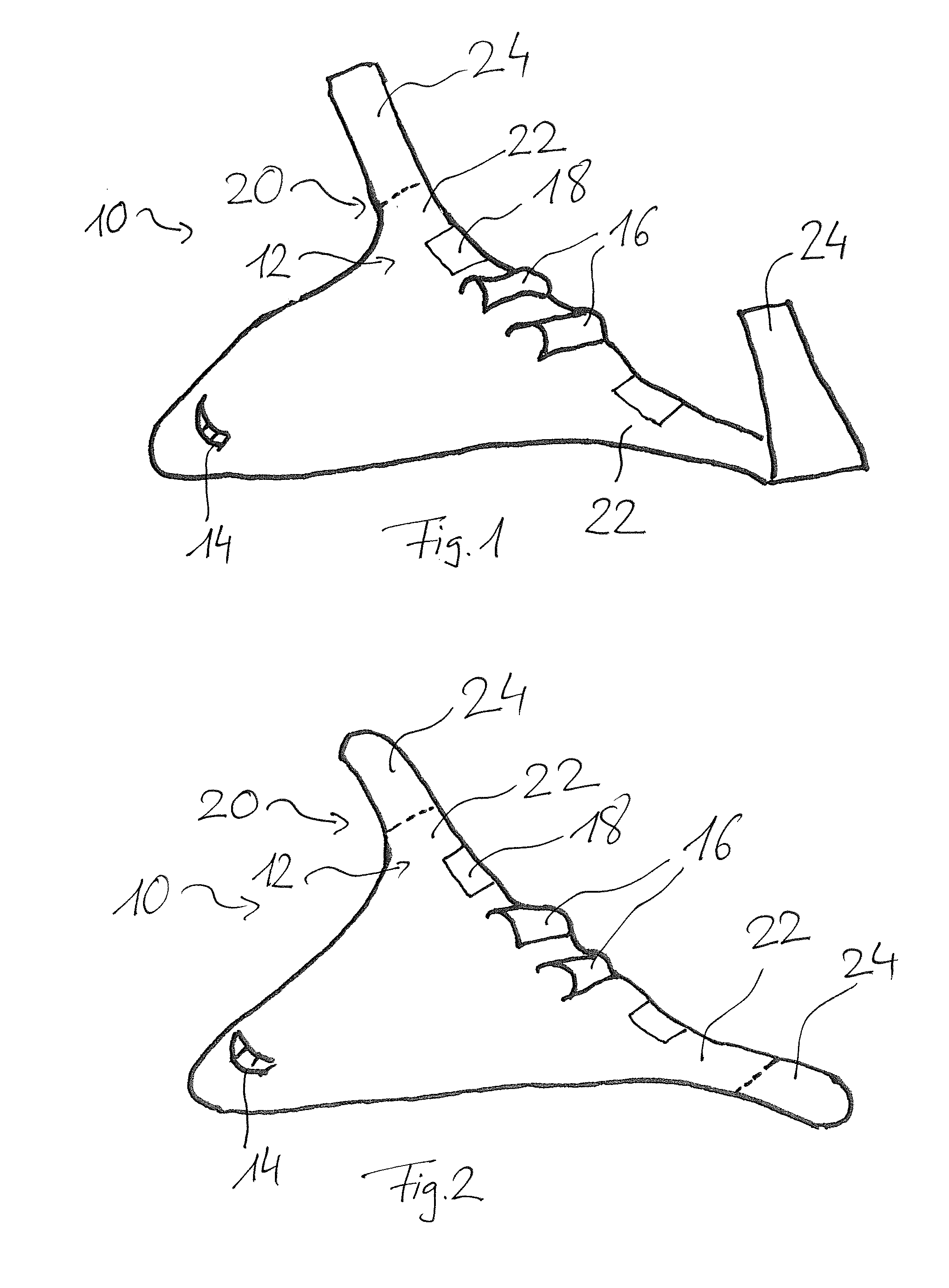
[0089]FIG. 1 shows an aircraft 10. The aircraft 10 is a blended wing body aircraft. The air-craft 10 comprises a wing 12, a cockpit 14 and jet engines 16. The cockpit 14 is arranged in a middle part of the wing 12. The jet engines 16 are also arranged in the middle part of the wing 12. The wing also comprises two elevators 18.

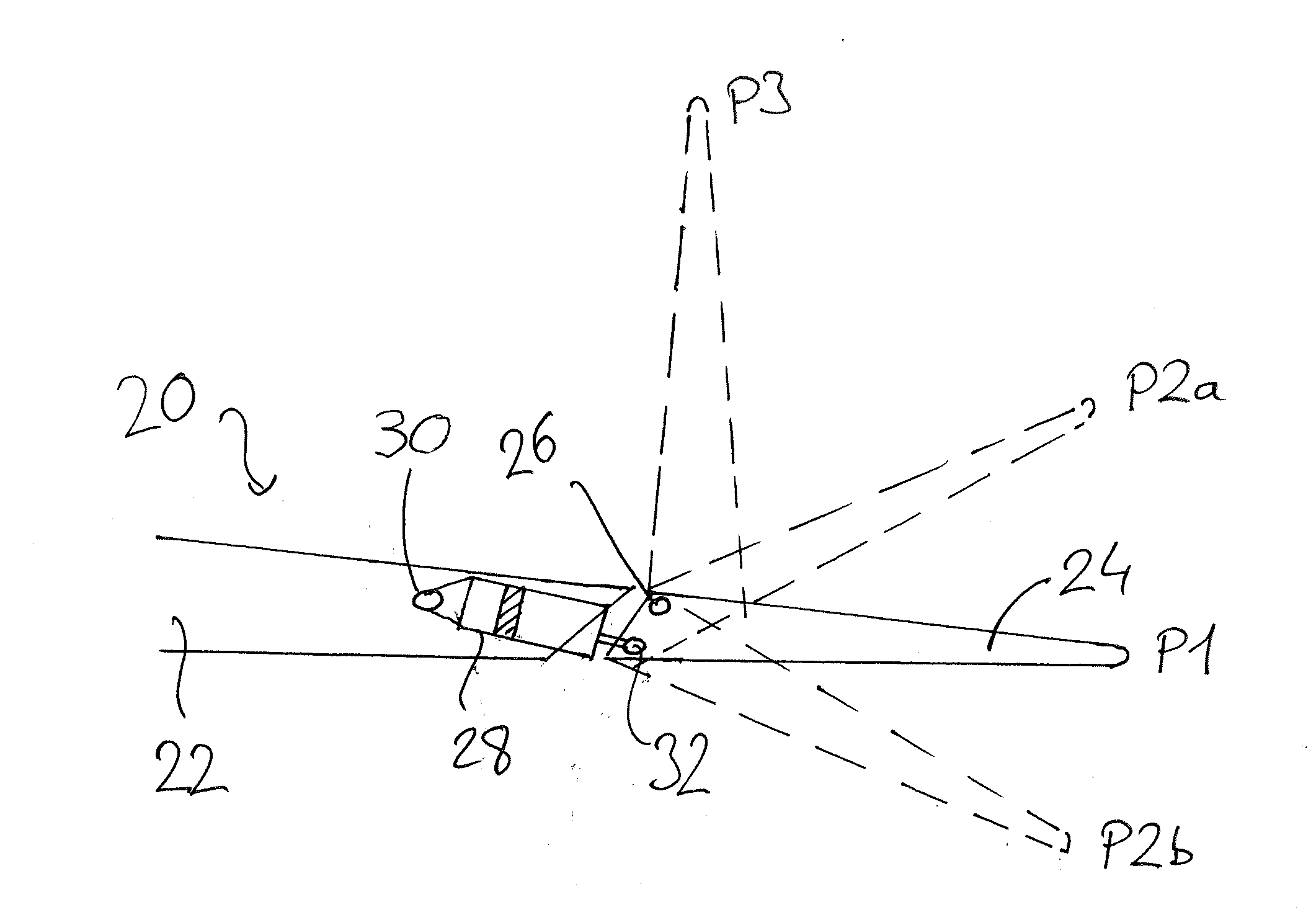
[0090]The wing 12 further comprises a wing assembly 20 including a first component 21, a first wing section 22, and a second component 23, a second wing section 24. The second wing section 24 can rotate with regard to the first wing section 22 by means of a hinge 26. In FIG. 1, the second wing section 24 is folded with regard to the first wing section 22. In FIG. 2, the first wing section 22 and the second wing section 24 are in a straight configuration.

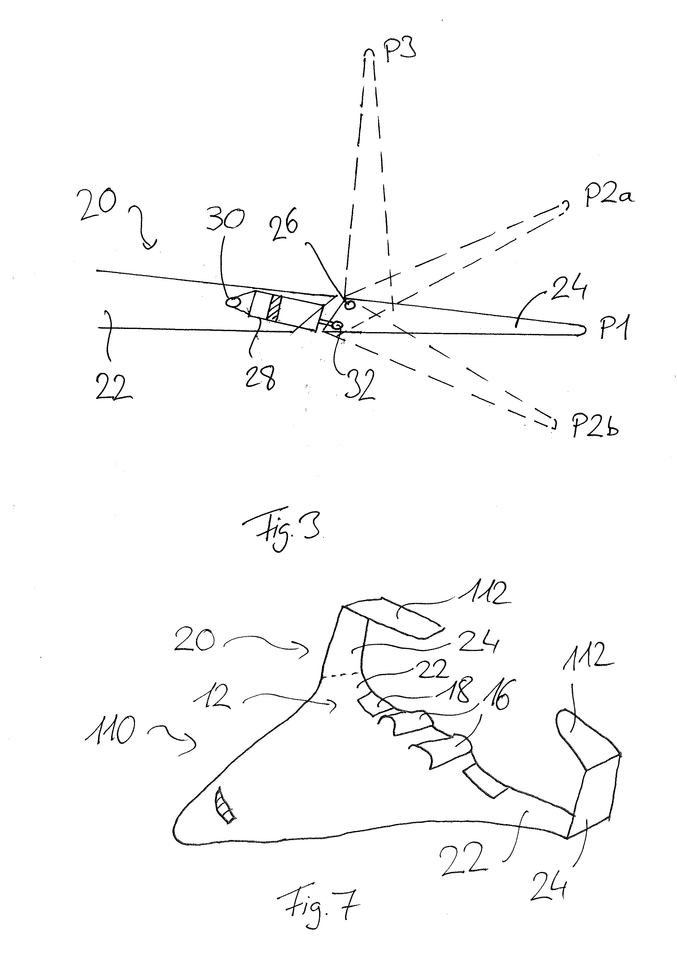
[0091]FIG. 3 shows an enlarged representation of the wing section 20. The second wing section 24 is rotatably attached to the first wing section 22 by means of the hinge 26. Hence, the second wing section 24 can...


PUM


Abstract

A coupling device for supporting a first wing section against a second wing section of an aircraft, and configured for passive flight load alleviation includes a housing including a chamber including a first portion and a second portion and filled with a fluid, a piston device movably arranged in the chamber and separating the first portion from the second portion in a fluid tight manner, a first fluid pathway connecting the first portion to the second portion, a first pressure relief valve arranged in the first fluid pathway and blocking the first fluid pathway, if the pressure in the second portion is smaller than a first relief pressure and opening the first fluid pathway, if the pressure in the second portion is greater than the first relief pressure. In addition, the coupling device can be used to actuate the second wing section against the first wing section.

Description

FIELD OF THE INVENTION[0001]The invention refers to a coupling device for supporting a first component against a second component of an aircraft, wherein the first component and the second component are movable relative to each other and exposed to aerodynamic loads. The coupling device is configured for a passive flight load alleviation. In addition, the invention refers to a wing assembly for an aircraft that comprises a first wing section and a second wing section that is rotatably attached to the first wing section. Furthermore, the invention refers to an aircraft that comprises at least one wing assembly.BACKGROUND OF THE INVENTION[0002]Wings of aircrafts that have a large span width facilitate high fuel efficiency. Possible issues arising with very large wing spans may be associated with the structure of the wings as they become very heavy in order to be able to carry the wing bending loads caused by maneuvers and gusts. To this end, some wings are divided in a first wing sect...

Claims


Application Information

Patent Timeline
Patent Type & Authority Applications(United States)
IPC IPC(8): B64C3/38B64C39/00B64C13/40B64C3/56
CPCB64C3/38B64C3/56B64C2039/105B64C13/40B64C39/00B64C3/42F15B15/149F15B15/204
Inventor WILDSCHEK, ANDREASSTORM, STEFANROLSTON, STEPHENHERRING, MARTIN
Owner AIRBUS DEFENCE & SPACE
Why Eureka
Try Eureka