Ball Screw

Active Publication Date: 2017-01-26
NSK LTD
View PDF2 Cites 5 Cited by
  • Summary
  • Abstract
  • Description
  • Claims
  • Application Information

AI Technical Summary

Benefits of technology

[0027]According to one aspect of the present invention, it is possible to provide a ball screw, which achieves a high cooling efficiency, which prevents leakage of

Problems solved by technology

Here, the shaft center cooling type may have a drawback in cost for making a hollow hole in the

Method used


Image

  • Ball Screw
  • Ball Screw
  • Ball Screw

Examples


Example

[0031]Embodiments of the present invention will now be described with reference to the drawings.

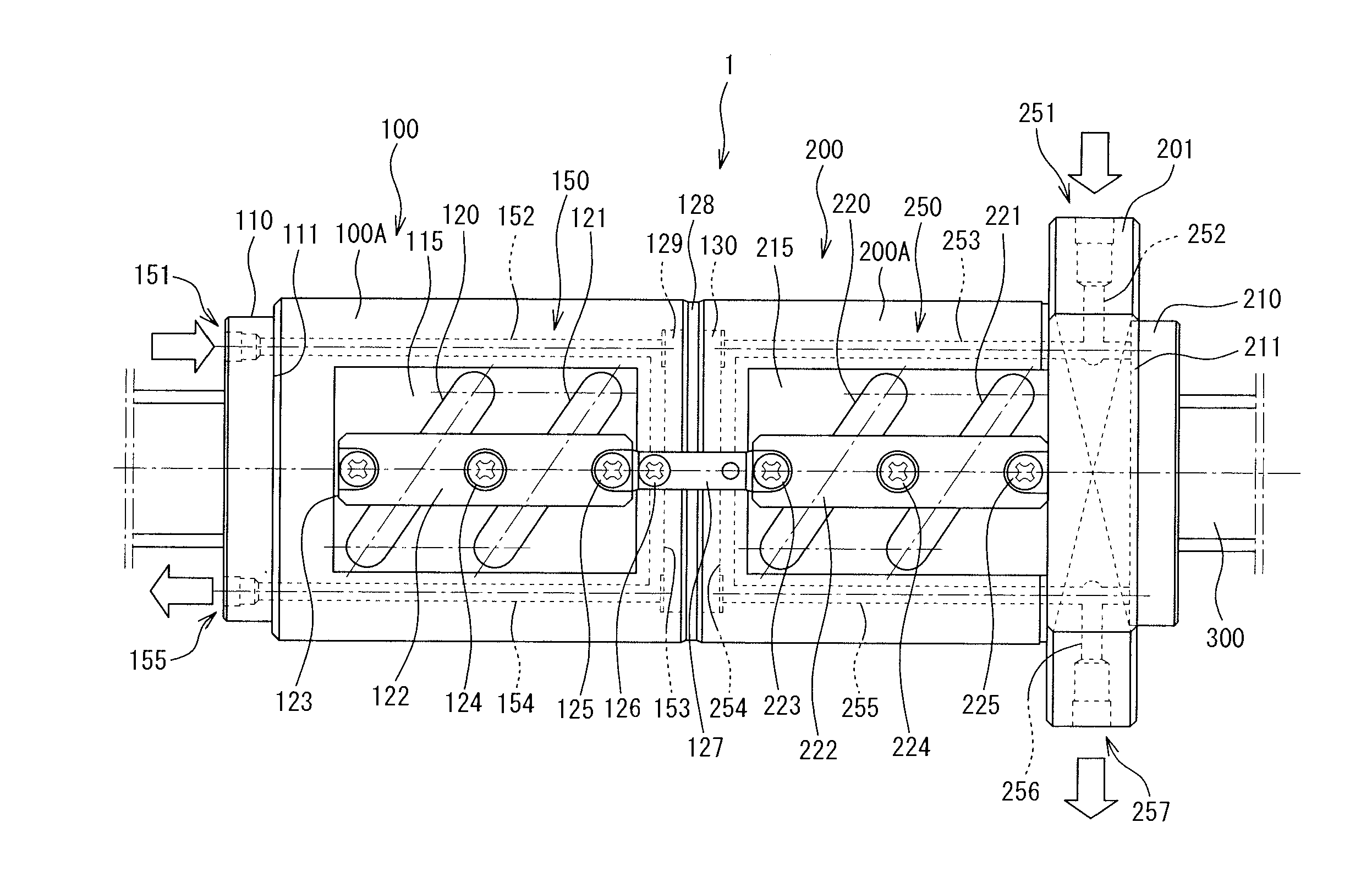
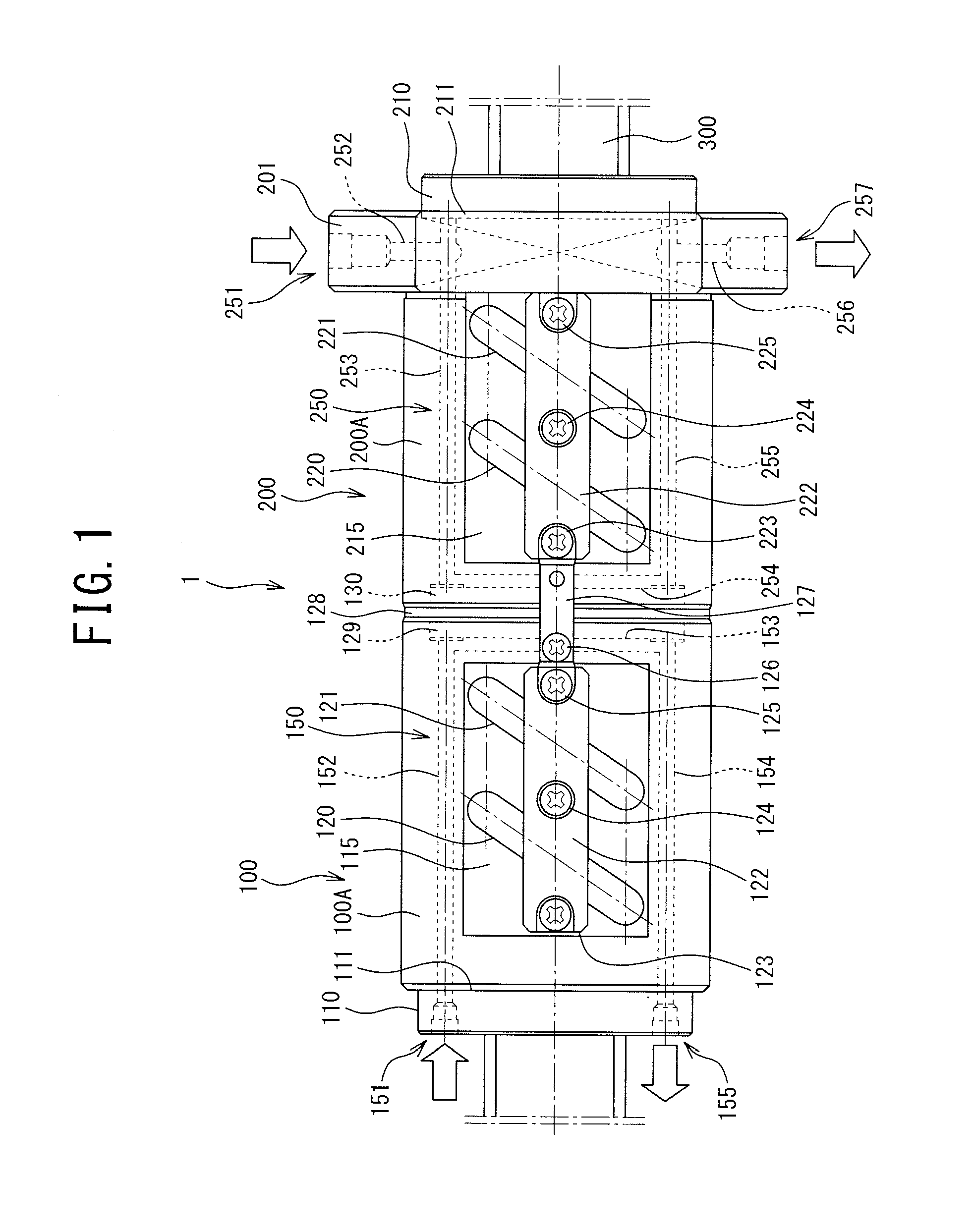
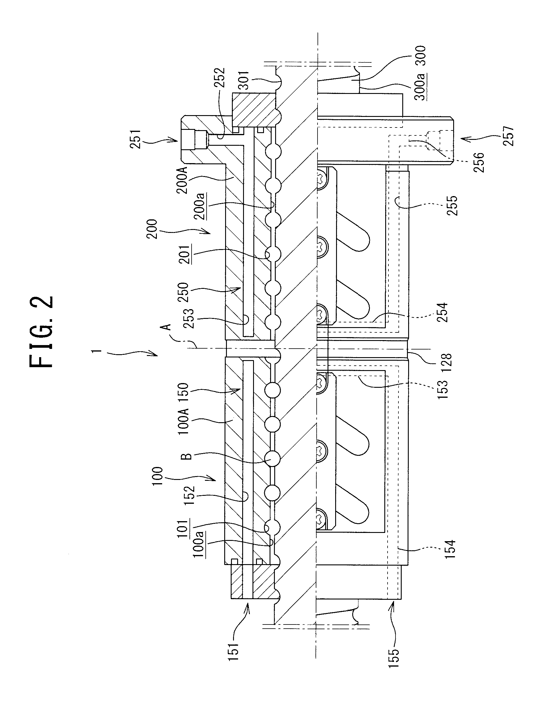
[0032]FIG. 1 is a side view of a configuration of a ball screw in one embodiment of the present invention. FIG. 2 is a partial sectional view of a configuration of the ball screw in one embodiment of the present invention. FIG. 3 is a side view of a configuration of the ball screw in one embodiment of the present invention, and flow channels are highlighted by hatching.

[0033]As illustrated in FIG. 1, a ball screw 1 in one embodiment of the present embodiment includes two nuts (which are a first nut 100 and a second nut 200), a screw shaft 300, and a preload application member which is provided between the two nuts and which is configured to apply preload to the ball.

Nuts

[0034]The first nut 100 includes a body portion 100A cylindrically formed to have an inside diameter larger than the outside diameter of the screw shaft 300, a cap 110, and tubes 120 and 121. The cap 110 is attached to one...


PUM


Abstract

There is provided a ball screw that is used to apply a preload to balls and that has a configuration of achieving a balance between the cooling efficiency and ease of assembly and disassembly. To this end, the ball screw includes a screw shaft, and a plurality of nuts movable relative to the screw shaft in an axial direction. Each of the nuts includes flow channels, which are cooling mechanisms and which respectively serve as independent channels to allow a cooling medium to pass through them. These flow channels are provided symmetrically with respect to a space between the nuts, and are configured so that the cooling medium can independently circulate in each of the nuts.

Description

TECHNICAL FIELD[0001]The present invention relates to ball screws, more particularly to a ball screw having a function to cool a nut.BACKGROUND ART[0002]There has heretofore been known a ball screw which includes a screw shaft, and a nut that is screwed to the screw shaft via plural rolling elements (e.g., balls) and in which the screw shaft and the nut are relatively rotatable. In this ball screw, frictional heat resulting from a point contact or surface contact is generated between the screw shaft and the nut during rotation. Hence, a cooling portion to reduce the frictional heat is provided in some cases.[0003]Types of installing the cooling portion in the conventional ball screw include a shaft center cooling type and a nut cooling type. The shaft center cooling type is a configured such that the screw shaft is a cooling target so that the cooling portion is provided in the screw shaft. As an example of this shaft center cooling type, the screw shaft is hollow to allow a cooling...

Claims


Application Information

Patent Timeline
IPC IPC(8): F16H57/04F16H25/24F16H25/22
CPCF16H57/0497F16H25/2418F16H57/0412F16H25/2209
Inventor MINAKUCHI, JUNJINAGAI, YUTAKASHINDO, MASASHI
Owner NSK LTD
Why Eureka
Try Eureka