Cooling unit, electronic apparatus rack, cooling system, and construction method thereof

Inactive Publication Date: 2010-02-11
HITACHI INFORMATION & TELECOMM ENG LTD
View PDF0 Cites 54 Cited by
  • Summary
  • Abstract
  • Description
  • Claims
  • Application Information

AI Technical Summary

Benefits of technology

[0021]According to the present invention, by introducing coolant into a cooling unit installed for an electronic apparatus, a higher cooling efficiency is achieved in the cooling unit, electronic apparatus cooling structure and electronic apparatus cooling system.
[0022]In addition, th

Problems solved by technology

In this approach, the rack cooling efficiency is low and power consumption is unavoidably increased.
However, in both the techniques, the apparatus inside the rack which has become hot is cooled by blowing cold air and the cooling efficiency is not high.
Also in these techniques, cold air or hot air or exhaust air is led into the server rack, which necessitates considerable design change in the server rack inner structure and/or change in the loca

Method used


Image

  • Cooling unit, electronic apparatus rack, cooling system, and construction method thereof
  • Cooling unit, electronic apparatus rack, cooling system, and construction method thereof
  • Cooling unit, electronic apparatus rack, cooling system, and construction method thereof

Examples


Example

[0033]Next, an embodiment of the present invention will be described referring to the accompanying drawings.

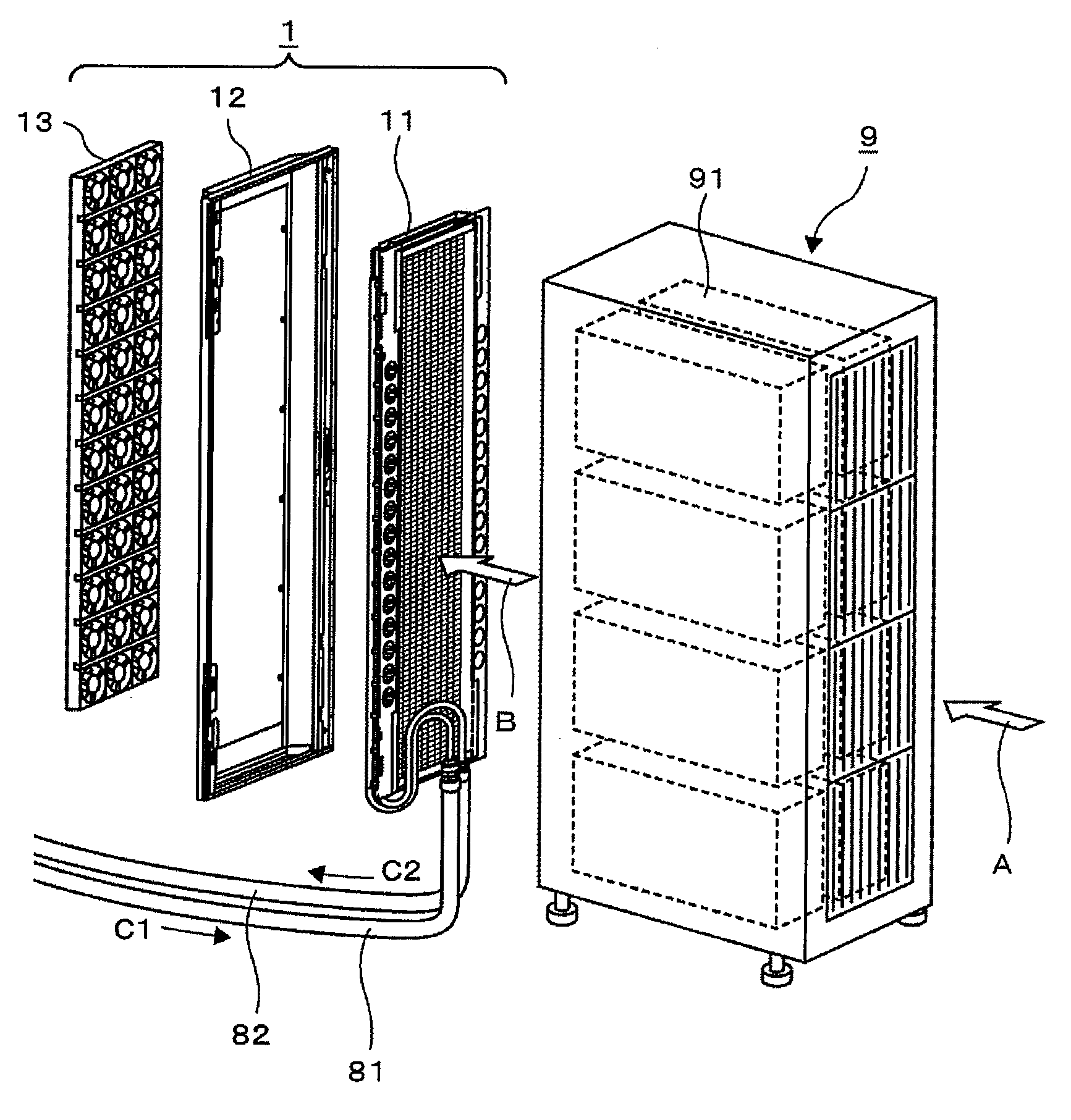
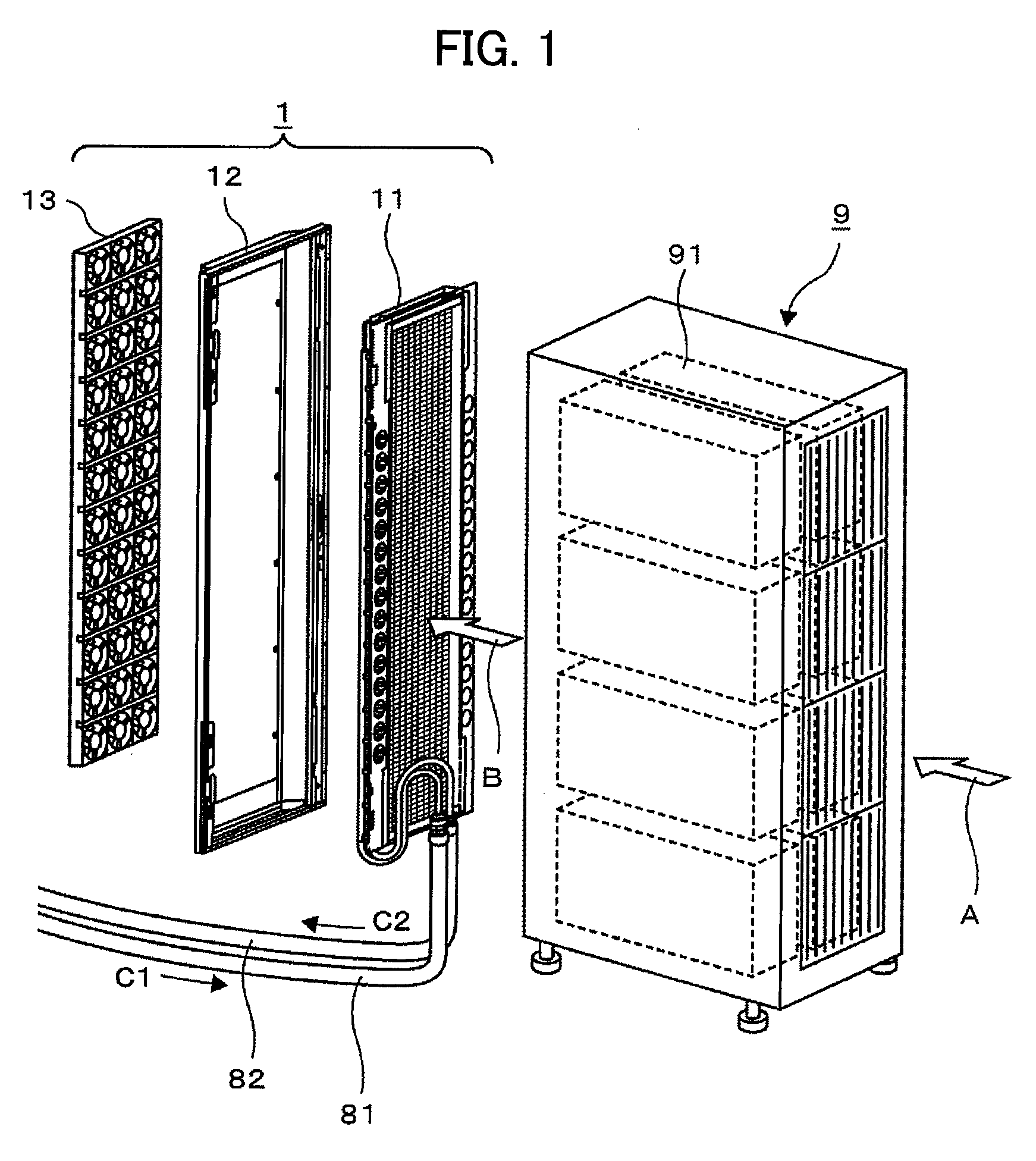
[0034]FIG. 1 shows a server rack cooling structure.

[0035]A cooling unit 1 is attached to the back of a server rack 9. The server rack 9 houses plural blade servers 91, for example, eight in total on its four shelves with two on each shelf. Each of the blade servers 91 is an electronic apparatus housing electronic components such as a CPU, memory, hard disk and power supply and blower fan where the power supply and memory are heat sources. In the server rack 9, installed in a server room, the blower fan of each blade server takes in cooling air from ahead of the blade server or apparatus (direction indicated by arrow A) and discharges the air heated therein (hot air) through the back of the apparatus (exhaust ventilation side) to the outside of the apparatus (direction indicated by arrow B).

[0036]The server rack 9 may have a conventional structure. Originally the conventional s...


PUM

PropertyMeasurementUnit
Sizeaaaaaaaaaa

Abstract

A cooling unit which improves the cooling efficiency of a server rack and minimizes rise in the server room temperature. A cooling unit for a server rack housing a server with a heat source includes: a fan unit having an array of fans for discharging hot air generated by the heat source from the rack; and a radiator unit having an array of pipes for guiding coolant to remove heat from the hot air discharged from the rack by rotation of the fans; and a frame unit which integrally combines the fan unit and the radiator unit. The cooling unit constructs a back door from which the hot air inside the rack is discharged.

Description

CLAIM OF PRIORITY[0001]The present application claims priority from Japanese patent application JP 2008-205804 filed on Aug. 8, 2008, the content of which is hereby incorporated by reference into this application.FIELD OF THE INVENTION[0002]The present invention relates to a cooling unit, an electronic apparatus rack, a cooling system and construction methods thereof, and in particular, relates to a cooling panel for cooling a server rack with coolant, a cooling structure of the server rack, a server cooling system and a construction method thereof.BACKGROUND OF THE INVENTION[0003]A conventional technique of cooling a server rack is for an example a rack cooling structure disclosed in JP-A No. 2004-63755 in which cold air sent from an air conditioning unit is supplied to an air supply port on a lower part of the rack to cool an apparatus inside the rack and the air heated by the apparatus and discharged from an exhaust port on an upper part of the rack is sent back to the air condit...

Claims


Application Information

Patent Timeline
IPC IPC(8): H05K7/20B21D53/02
CPCY10T29/4935H05K7/20745H04B1/036H05K7/20H05K7/18F28D1/03
Inventor MIYAZAWA, TOMOYUKIARAYA, TAKESHIIDEI, AKIOIWATA, HIROSHIIETA, KANAMEEBATO, TSUYOSHI
Owner HITACHI INFORMATION & TELECOMM ENG LTD
Why Eureka
Try Eureka