Lamination coil component and coil module

a technology of lamination coil and component, applied in the direction of transformer/inductance details, fixed inductances, inductances, etc., can solve the problem that the direct-current superposition characteristics change in accordance with the temperature, the reduction of inductance due to magnetic saturation cannot be sufficiently suppressed, and the problem of increasing the burden on the designer, so as to improve the direct-current superposition characteristics, the effect of improving the burden

Inactive Publication Date: 2017-01-26
MURATA MFG CO LTD
View PDF7 Cites 16 Cited by
  • Summary
  • Abstract
  • Description
  • Claims
  • Application Information

AI Technical Summary

Benefits of technology

[0007]Preferred embodiments of the present invention provide a lamination coil component capable of improving direct-current superposition characteristics in a stable manner.
[0019]In a coil module according to a preferred embodiment of the present invention, the air gap provided in the multilayer body so as to improve the direct-current superposition characteristics is not magnetized by magnetic flux. This makes it possible to improve the direct-current superposition characteristics in a stable manner. In addition, because a variation in the direct-current superposition characteristics with respect to a change in temperature of the multilayer body is able to be easily estimated, an increase in the burden on the designer caused by diversification in thickness of the air gap, the number thereof, and other factors is effectively reduced or prevented.

Problems solved by technology

However, in the above-mentioned related art, since the magnetic ceramic layers and the nonmagnetic ceramic layer are calcined at the same time, a diffusion layer (which is not a nonmagnetic layer) is formed between the magnetic layer and the nonmagnetic layer or the nonmagnetic layer itself is magnetized, wherein a reduction in inductance due to magnetic saturation cannot be sufficiently suppressed.
This degrades the direct-current superposition characteristics in some cases.
The problem that the direct-current superposition characteristics change in accordance with the temperatures becomes further complicated as the thickness of the nonmagnetic ceramic layer, the number of layers, and so on are diversified.

Method used


Image

  • Lamination coil component and coil module
  • Lamination coil component and coil module
  • Lamination coil component and coil module

Examples


first preferred embodiment

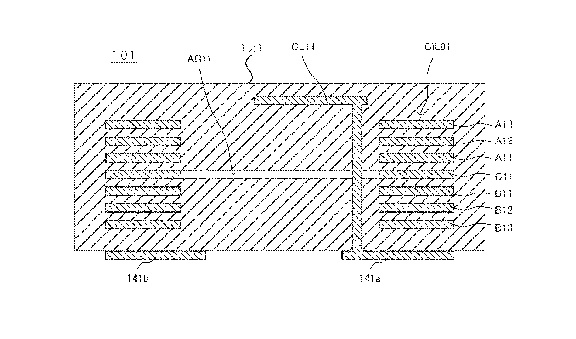
[0065]Referring to FIG. 2, a lamination coil component (LGA inductor) 101 according to a first preferred embodiment of the present invention includes a multilayer body 121 in which a plurality of magnetic body sheets are laminated. A coil conductor B13, a coil conductor B12, a coil conductor (a first coil conductor) B11, a coil conductor (additional coil conductor) C11, a coil conductor (a second coil conductor) A11, a coil conductor A12, and a coil conductor A13, each of which preferably has a band shape, for example, are embedded in the multilayer body 121. In addition, a wiring conductor CL11 is also embedded therein.

[0066]Preferably, the coil conductors B13, B12, B11, C11, A11, A12, and A13 are aligned or substantially aligned in that order in the lamination direction, and are connected in series so as to define a single coil CIL01. The coil conductors B13, B12, B11, A11, A12, and A13 preferably define a circle when viewed in the lamination direction, and the coil conductor C11 ...

second preferred embodiment

[0074]Referring to FIG. 11, a lamination coil component (LGA inductor) 102 according to a second preferred embodiment of the present invention includes a multilayer body 122 in which a plurality of magnetic body sheets are laminated. A coil conductor (first coil conductor) B21, a coil conductor (additional coil conductor) C21, and a coil conductor (second coil conductor) A21, each of which preferably has a band shape, for example, are embedded in the multilayer body 122. Preferably, the coil conductors B21, C21, and A21 are aligned or substantially aligned in the lamination direction in that order, and are connected in series to define a single coil CIL02. Preferably, the coil conductors B21 and A21 define a circle when viewed in the lamination direction, and the coil conductor C21 extends along the circle. As such, the coil CIL02 is preferably embedded in the multilayer body 122 such that a winding axis thereof preferably extends in the lamination direction.

[0075]FIG. 12A illustrat...

third preferred embodiment

[0083]Referring to FIG. 14, a lamination coil component (LGA inductor) 103 according to a third preferred embodiment of the present invention preferably includes a multilayer body 123 in which a plurality of magnetic body sheets are laminated. A coil conductor (specific coil conductor) B31, a coil conductor (additional coil conductor) C31, and a coil conductor (specific coil conductor) A31, each of which preferably has a band shape, for example, are embedded in the multilayer body 123. In addition, a wiring conductor CL31 is also embedded in the multilayer body 123. Preferably, the coil conductors B31, C31, and A31 are aligned or substantially aligned in the lamination direction in that order, and are connected in series to define a single coil CIL03. The coil conductors B31 and A31 preferably define a circle when viewed in the lamination direction, and the coil conductor C31 extends along the circle. As such, the coil CIL03 is embedded in the multilayer body 123 such that a winding...


PUM

PropertyMeasurementUnit
magneticaaaaaaaaaa
sizeaaaaaaaaaa
distancesaaaaaaaaaa

Abstract

A multilayer body includes a plurality of magnetic body sheets laminated in a lamination direction. Coil conductors are embedded in the multilayer body to define a coil with a winding axis extending in the lamination direction. The coil conductors define a circle when viewed in the lamination direction. An air gap is provided in a region surrounded by an inner circumferential edge of the circle defined by the coil conductors when viewed in the lamination direction. The coil conductors sandwich the air gap therebetween in the lamination direction and are surrounded by the magnetic body without being exposed to the air gap.

Description

CROSS REFERENCE TO RELATED APPLICATIONS[0001]This application claims the benefit of priority to Japanese Patent Application No. 2014-080017 filed Apr. 9, 2014 and is a Continuation Application of PCT / JP2015 / 055594 filed on Feb. 26, 2015. The entire contents of each of these applications are hereby incorporated by reference herein.BACKGROUND OF THE INVENTION[0002]1. Field of the Invention[0003]The present invention relates to lamination coil components and coil modules, and particularly relates to a lamination coil component including a multilayer body in which magnetic body layers are laminated and a coil that is embedded in the multilayer body, and a coil module including the lamination coil component.[0004]2. Description of the Related Art[0005]An example of this type of lamination coil component is disclosed in International Publication No. WO 2008 / 093568, and describes a lamination coil component includes a multilayer body 11 (11a, 11b) in which magnetic layers made of magnetic ...

Claims


Application Information

Patent Timeline
Patent Type & Authority Applications(United States)
IPC IPC(8): H01F27/28H01F27/245
CPCH01F27/2804H01F2027/2809H01F27/245H01F3/14H01F17/0013H01F2017/0066
Inventor NAKANIWA, MASATAKA
Owner MURATA MFG CO LTD
Why Eureka
Try Eureka