Massage structure for backpack

a backpack and massage technology, applied in the field of massage devices, can solve the problems of reducing the blood flow to the shoulder and fingers, affecting the local circulation, so as to improve the local blood circulation

Inactive Publication Date: 2017-02-02
LIN JIEN WAY
View PDF19 Cites 20 Cited by
  • Summary
  • Abstract
  • Description
  • Claims
  • Application Information

AI Technical Summary

Benefits of technology

[0008]Accordingly, it is the primary object of the present invention to provide a massage structure for a backpack that is able to perform massage, and thus thereupon substantially improve the local blood circulation at the back of the carrier.

Problems solved by technology

It is well known that carrying a heavy backpack can induce fatigue and reduce blood flow to the shoulder and fingers.
Typically, the backpack always includes straps that rest on an area of the body where they may compress auxiliary veins which cause an abnormal high blood pressure inside the veins and a subsequent decrease of blood flow in the shoulders and arms.
The abnormal blood flow caused by carrying backpacks would often cause the carrier to experience both fatigue and pain in the back.
Equally important, a localized temperature rise on the back caused by ill air ventilation between the backpack and the back of the carrier would further make worse the blood circulation of carrier's back that is already compressed to flow abnormally.

Method used


Image

  • Massage structure for backpack
  • Massage structure for backpack
  • Massage structure for backpack

Examples


first embodiment

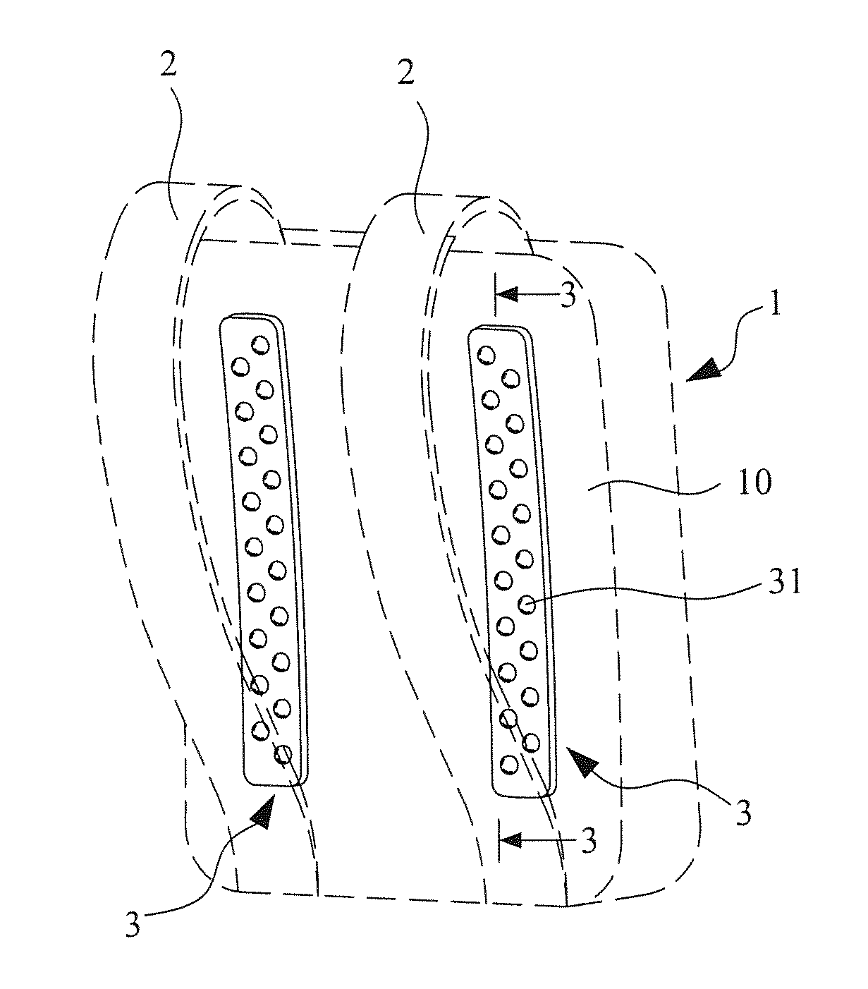
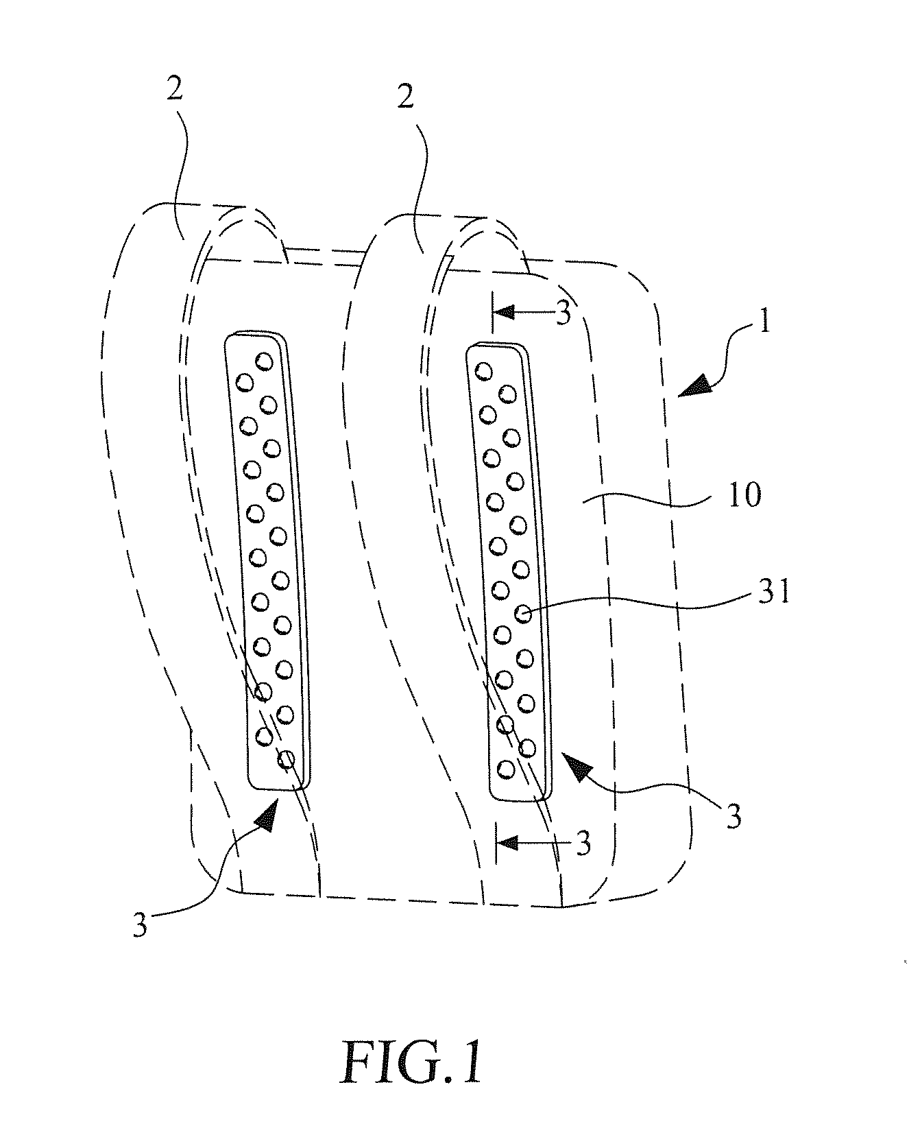
[0025]As shown, the massage unit 3 of the present invention is basically formed as a pad structure adapted to be mounted onto the back portion 10 of the backpack 1. In the present invention, the massage unit 3 is formed as a structure having two parallel pads lining vertically on the back portion 10 of the backpack 1.

[0026]Referring to FIG. 3, it is a cross-sectional view taken along line 3-3 of FIG. 1. The massage unit 3 includes a base 30 and a plurality of protrusions 31 formed on the base 30. The base 30 is preferably made of flexible material. The protrusions 31 are protruded outward away from the base 30 with a predetermined height. The plurality of protrusions 31 are distributed in a predetermined discrete manner over the base 30.

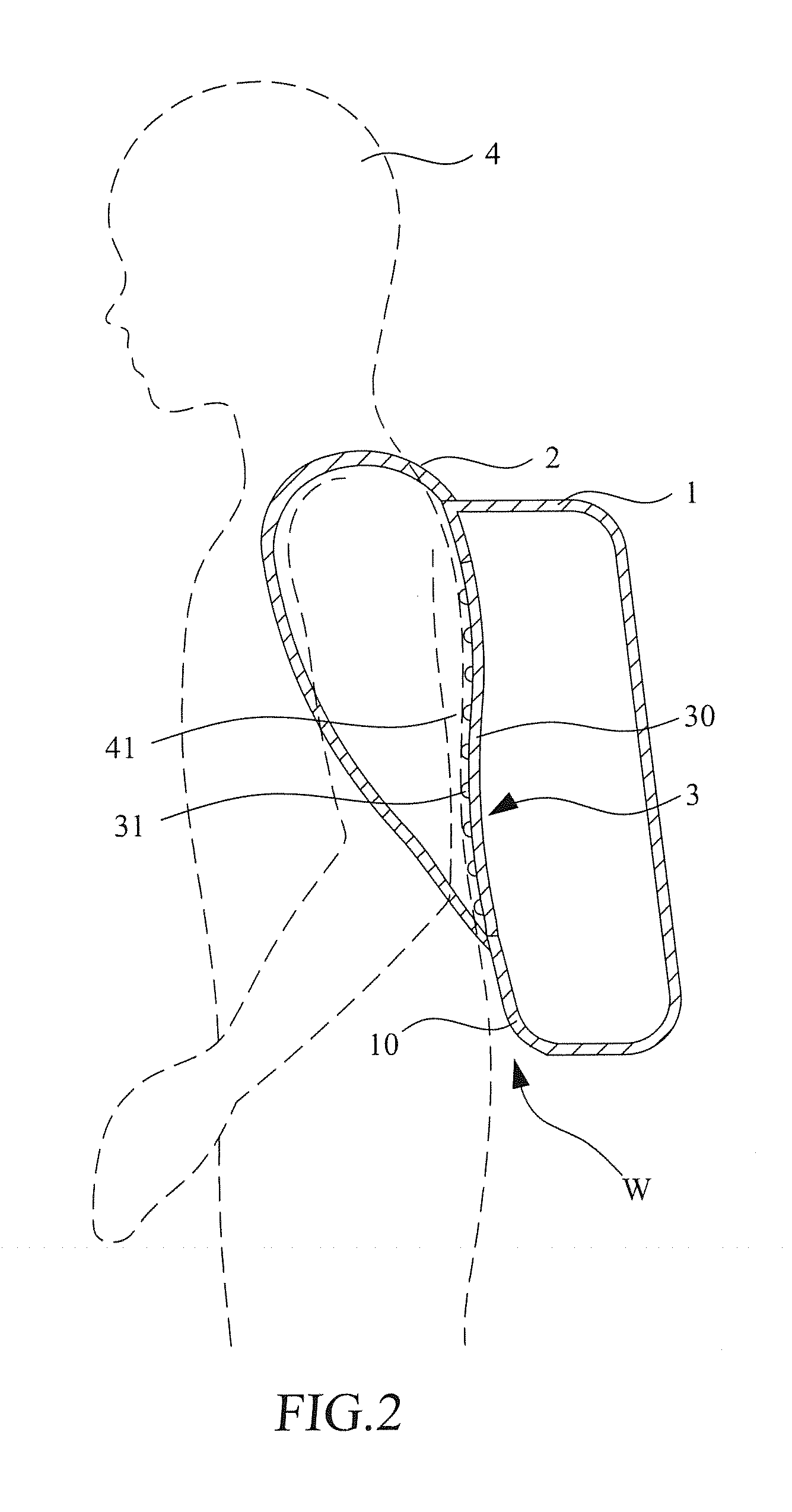
[0027]In addition, since the protrusions 31 of the massage unit 3 have heights to space the back portion 10 of the backpack 1 and the back 41 of the user 4, so that a ventilation space W between the back portion 10 of the backpack 1 and the back 41 o...

second embodiment

[0034]Referring now to FIG. 8, a schematic view of the massage structure for a backpack in accordance with the present invention is shown. FIG. 9 is a schematic side view showing the backpack of FIG. 8 is carried by a user.

[0035]The instant embodiment comprises constituent components / parts that are similar to those of the first embodiment and similar components / parts are designated with the same reference numerals for consistency. In the instant embodiment, a difference from the first embodiment is that the massage unit 3 further comprises an extended base 50 upward extended from a top end 35 of the base 30 to the strap 2 of the backpack 1. The extended base 50 is also provided with a plurality of extended protrusions 51 thereon.

[0036]The extended protrusions 51 are protruded outward away from the extended base 50 with a predetermined height for applying a massage onto a shoulder 43 of the user 4 or applying a stimulation right at a shoulder acupoint 44 of the shoulder 43 of the use...


PUM


Abstract

A massage structure to be mounted onto a back portion of a backpack includes a base and a plurality of protrusions. The plurality of protrusions are distributed in a predetermined discrete manner over the base and arranged to align with at least one specific acupoint on a back of a user. Each of the protrusions protrudes outwards away the back portion from the base with a predetermined height for applying massage onto the back of the user carrying the backpack. The massage structure further includes a pair of extended bases upward extended from a top end of each base to the straps of the backpack respectively, and a plurality of extended protrusions formed on the extended bases and arranged to align with at least one specific shoulder acupoint on a shoulder of the user.

Description

BACKGROUND OF INVENTION[0001]1. Field of the Invention[0002]The invention relates to a massage device, more particularly to a massage structure that can be integrated into a backpack to perform massage in the back of a carrier of the backpack.[0003]2. Description of the Prior Art[0004]It is well known that carrying a heavy backpack can induce fatigue and reduce blood flow to the shoulder and fingers. Empirically, a rough estimate states that blood flow through large and small blood vessels in the upper body will drop nearly 50% in adults carrying backpacks weighing 11.8 kg for ten minutes.[0005]Typically, the backpack always includes straps that rest on an area of the body where they may compress auxiliary veins which cause an abnormal high blood pressure inside the veins and a subsequent decrease of blood flow in the shoulders and arms. Namely, the blood flow of the large and small vessels of the upper extremity area of the body would decrease in an individual while wearing a backp...

Claims


Application Information

Patent Timeline
Patent Type & Authority Applications(United States)
IPC IPC(8): A61H7/00A45F3/04A61H39/04
CPCA61H7/001A61H39/04A61H2201/1652A61H2205/081A45F3/04A61H2201/1614A45F4/02A61H7/002A45F2003/122A45F2003/127A61H2201/1253A61H2201/1623A61H2201/165A61H2201/1695
Inventor LIN, JIEN-WAY
Owner LIN JIEN WAY
Why Eureka
Try Eureka