System for draining and refilling cryogenic fuel in a vehicle tank

a vehicle tank and cryogenic fuel technology, applied in the direction of vehicle maintenance, container discharging methods, transportation and packaging, etc., can solve the problems of increased safety risks, flaming, fire hazards, etc., and achieve high safety, quick and efficient draining of the vehicle tank, and reduce the cost of vehicle servicing

Active Publication Date: 2017-02-02
VOLVO LASTVAGNAR AB
View PDF9 Cites 14 Cited by
  • Summary
  • Abstract
  • Description
  • Claims
  • Application Information

AI Technical Summary

Benefits of technology

[0040]The described tool makes it possible to quickly and efficiently drain the vehicle tank, for example, when servicing the commercial vehicle in a workshop, so that service work is enabled without an risk of ignition of the highly flammable cryogenic fuel. After completing the service work, the fuel can be returned to the tank after reversing the hoses as described herein, whereupon the workshop visit can be terminated. By means of insulated cooling tanks and possibly also insulated conduits, the temperature of the cryogenic fuel in gaseous form can be held below the boiling point of the fuel, for example below −163 degrees Celsius as the fuel primarily consists of methane.
[0041]Both draining of a vehicle tank and returning of cryogenic fuel to the vehicle tank can be carried out rapidly and smoothly and with high safety with the herein described tool. The entire process of draining the tank, including time for setup, takes about 30 minutes up to one hour. The refilling of the tank takes an equal amount of time. This should be compared to the hitherto used method for draining a tank of cryogenic fuel by burning off the fuel under constant supervision, a process which may take several hours if there is lot of fuel left in the tank to be drained. Accordingly, the herein described tool enables a considerable time saving, which of course greatly reduces the costs for vehicle servicing, both with regard to labour costs and with regard to the loss of income incurred when the vehicle is idle for a service operation. It is also important from a fuel economy point of view to reduce the time elapsing while the fuel is stored outside the vehicle, before it is returned to the vehicle for continued use. Even if the refrigerated, pressurized fuel is stored in insulated cooling tanks, the temperature in the tanks will rise over time and the fuel will gradually be transformed into gaseous form. For safety reasons, the excess of gas produced is vented from the tank gradually, which results in a loss of fuel increasing as time goes on, if not special measures are taken to recover the vented fuel.

Problems solved by technology

It is common knowledge within the field that work with cryogenic gases poses a fire hazard, since the gases may be highly flammable.
When using cryogenic fuel as a power fuel in commercial vehicles, any shop work, such as service or repair of the vehicle, results in increased safety risks.
During repair or service potentially fire-causing equipment may be used, and in some cases flaming may be caused, e.g. by arc welding.
Draining a tank of cryogenic fuel is associated with difficulties, since the temperature has to be very low to keep the fuel in liquid form, at least down by −160 degrees relative to the temperature of the surroundings.
This procedure is time-consuming, since it may take several hours to burn off a few litres of fuel in liquid form.
Furthermore, the flame has to be monitored while burning, since the risk of accidents is obvious.
Consequently, this is both time and work consuming.
Also, the procedure has to be carried out under protected conditions and while observing safety regulations, which can be problematic.
For example, it may be associated with difficulties to find the right safety distance in the area adjacent to a workshop.
In addition, when letting the fuel burn off, it represents a waste of resources since the fuel goes completely to waste.
As a result of this, an undesirably high overpressure can develop in both the vehicle tank and in the cooling tank of the tool.
However, venting of fuel results in a waste of resources since valuable fuel is wasted.
For instance, when servicing these, the tank could hold so much fuel that the cooling tank of the tool cannot hold the whole quantity of fuel.
Also in a normal-size tank, problems may arise in that the cooling tank of the tool cannot hold a sufficient quantity of fuel.
If, however, the refilling takes place as a normal refuelling during use of the vehicle, there may still be some liquid fuel left in the vehicle tank.
The refilling of the tank takes an equal amount of time.
For safety reasons, the excess of gas produced is vented from the tank gradually, which results in a loss of fuel increasing as time goes on, if not special measures are taken to recover the vented fuel.
A large and unwieldy tank can cause inconveniences in workshops with insufficient space and cramped premises.
Also, the fuel consumption of a fully loaded vehicle is of course higher.
Furthermore, it is space saving to have the cryogenic fuel in liquid form in the fuel tanks of the commercial vehicles.
In addition, costs can be planned as the tank volume is known.
Problems may arise when air enters the cold vehicle tank, since air contains water.
At the low temperature prevailing in the tank, water crystals are formed which ruin the system.
The gas is heavier than air up to −107 degrees, at higher temperatures the gas is lighter than air and rises and mixes with the air, which increases the risk of ignition.

Method used


Image

  • System for draining and refilling cryogenic fuel in a vehicle tank
  • System for draining and refilling cryogenic fuel in a vehicle tank
  • System for draining and refilling cryogenic fuel in a vehicle tank

Examples


Embodiment Construction

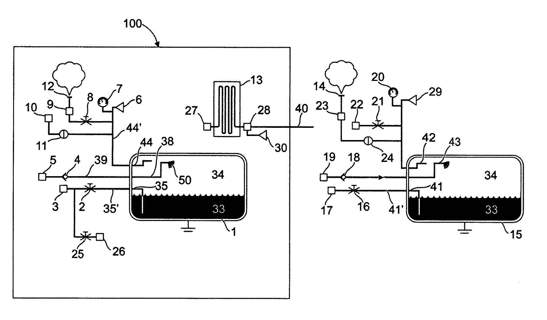
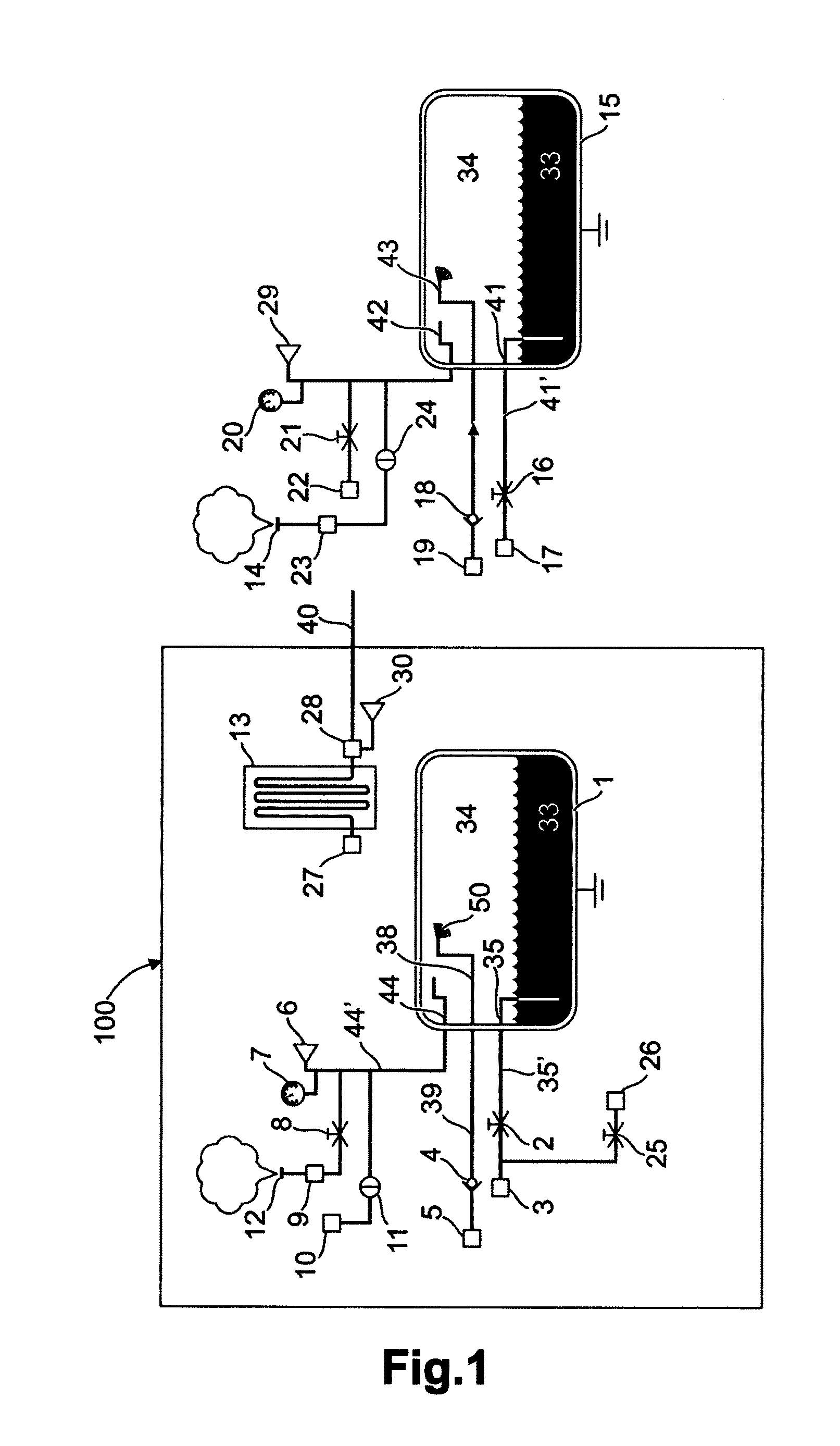
[0059]FIG. 1 shows a tool 100 for draining and refilling a vehicle tank 15 for cryogenic fuel 33, wherein the tool 100 comprises a heat exchanger 13 and a cooling tank 1, said cooling tank 1 exhibiting an outlet 35 to a fuel outlet conduit 35′ having at least one outlet valve 2, said fuel outlet 35 being connectable to a first fuel conduit and a second fuel conduit via the outlet valve 2 and a connecting device 3. The cooling tank 1 comprises a fuel inlet 38, which is connected to a fuel inlet conduit 39 via a check valve 4. The fuel inlet conduit 39 exhibits a connecting device 5 for connecting the fuel inlet 38 in the shown draining mode. In this mode, the fuel conduit 40 is connected to the heat exchanger 13 via a connecting means 28. The fuel conduit 40 is also adapted for connecting to the inlet 38 of the cooling tank 1 via a connecting means 5.

[0060]Fuel which is passed into one of the tanks 1, 15 is injected into the upper portion of the tank, for example by means of a sprayi...


PUM


Abstract

A tool for draining and refilling a vehicle tank for cryogenic fuel, wherein the tool when in position for use has a vertical direction and includes a heat exchanger and a cooling tank, the cooling tank having an upper portion and a lower portion as viewed in the vertical direction of the tool and including a fuel outlet having at least one outlet valve, the fuel outlet being connected to a first fuel conduit and second fuel conduit via the at least one outlet valve, wherein the first fuel conduit includes an arrangement for connecting the first fuel conduit to an inlet on the heat exchanger, and wherein the second fuel conduit includes an arrangement for connecting the second fuel conduit to an inlet on a vehicle tank, the cooling tank further including an inlet, the inlet being connected to a fuel inlet conduit via a check valve and the fuel inlet conduit including an arrangement for connecting the inlet to an outlet from the heat exchanger, or to an outlet from a vehicle tank, and the outlet of the heat exchanger including an arrangement for connecting to an inlet on a vehicle tank, and a system and method for draining and refilling a vehicle tank.

Description

BACKGROUND AND SUMMARY[0001]The present invention relates to a tool, a system and a method for draining and refilling cryogenic fuel in a vehicle tank.[0002]The invention can be applied to commercial vehicles, such as trucks, buses and work vehicles. Although the invention is described with reference to commercial vehicles, the invention is not limited to this type of vehicles, but can also be used on other vehicles such as work machines, e.g. excavators.[0003]It is common knowledge within the field that work with cryogenic gases poses a fire hazard, since the gases may be highly flammable. When using cryogenic fuel as a power fuel in commercial vehicles, any shop work, such as service or repair of the vehicle, results in increased safety risks. During repair or service potentially fire-causing equipment may be used, and in some cases flaming may be caused, e.g. by arc welding. Therefore, in order to minimize the risks when working on commercial vehicles of this kind, the cryogenic ...

Claims


Application Information

Patent Timeline
Patent Type & Authority Applications(United States)
IPC IPC(8): F17C7/02
CPCF17C7/02F17C2205/0352F17C2221/033F17C2223/0161F17C2225/0161F17C2270/0176F17C2227/0107F17C2227/0302F17C2265/032F17C2265/065F17C2270/0171F17C2225/035F17C2205/0355F17C2223/033F17C2225/033F17C2227/0393F17C2270/0178B60K2015/03315B60S5/02F17C7/00B60K2015/03473
Inventor TILANDER, MIKAEL
Owner VOLVO LASTVAGNAR AB
Why Eureka
Try Eureka