
Displacement measurement systems and methods

a technology of displacement measurement and measurement system, applied in the direction of girders, shock-proofing, joists, etc., to achieve the effect of prolonging the life of the power sour

Active Publication Date: 2017-02-02
COREBRACE LLC
View PDF3 Cites 13 Cited by
  • Summary
  • Abstract
  • Description
  • Claims
  • Application Information

AI Technical Summary

Benefits of technology

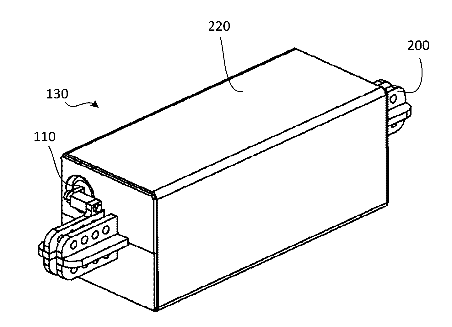
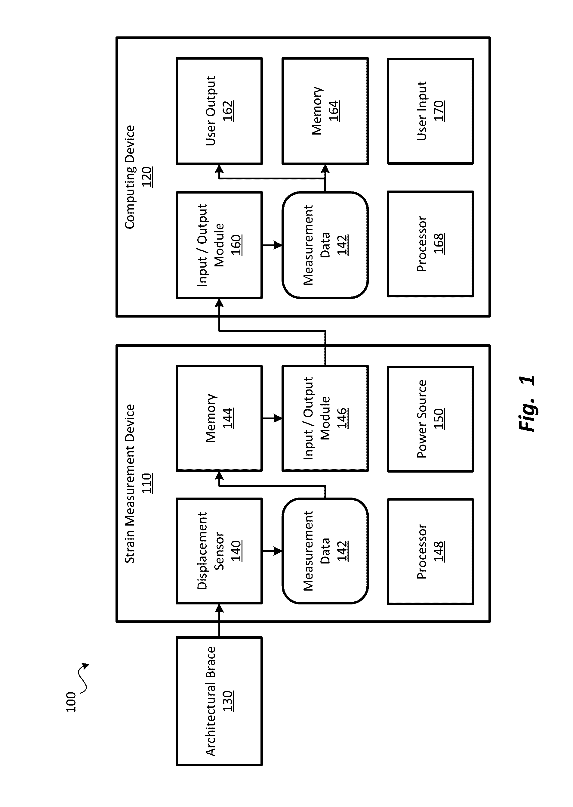
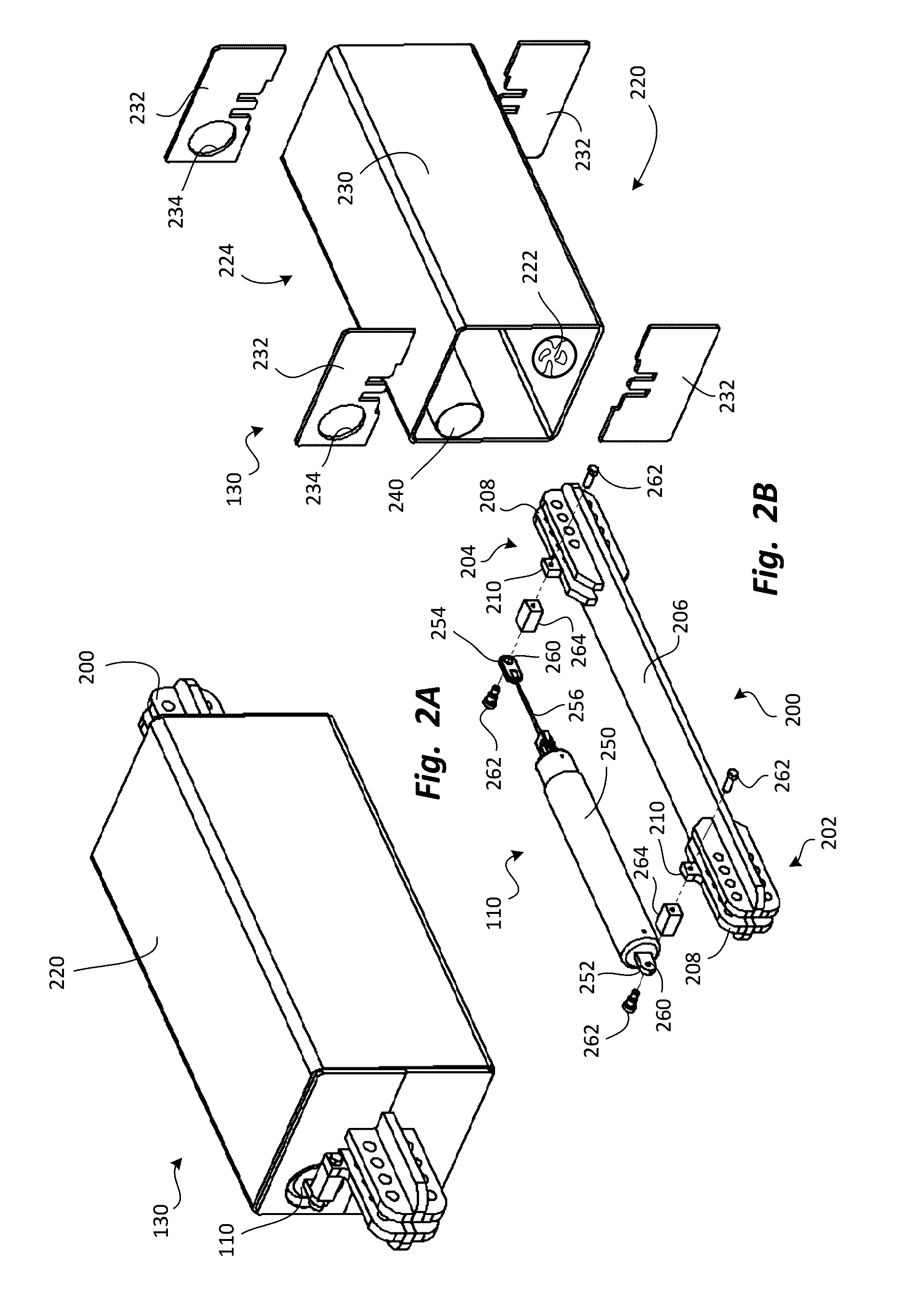
The patent describes a device that measures displacement, which can be used to detect changes in the shape of an object. The device has a battery power source that can provide power to the sensor. When a deformation occurs, the sensor detects it and switches to an active mode, where it generates measurement data. This helps to extend the life of the battery. The device can also store the measurement data and send it to a computing device through a communication module. The device is sealed to protect it from damage by cement dust and other particles that may be generated during deformation events. This makes it suitable for use in embedded applications.

Problems solved by technology

Further, such deformation inducing events may include wind storms, thermally-induced displacements, blast events, and the like.

Method used


Image

  • Displacement measurement systems and methods
  • Displacement measurement systems and methods
  • Displacement measurement systems and methods

Examples


Embodiment Construction

[0040]The presently preferred embodiments of the present invention can be understood by reference to the drawings, wherein like reference numbers indicate identical or functionally similar elements. It will be readily understood that the components of the present invention, as generally described and illustrated in the figures herein, could be arranged and designed in a wide variety of different configurations. Thus, the following more detailed description, as represented in the figures, is not intended to limit the scope of the invention as claimed, but is merely representative of presently preferred embodiments of the invention.

[0041]Moreover, the Figures may show simplified or partial views, and the dimensions of elements in the Figures may be exaggerated or otherwise not in proportion for clarity. In addition, the singular forms “a,”“an,” and “the” include plural referents unless the context clearly dictates otherwise. Thus, for example, reference to a terminal includes referenc...


PUM


Abstract

A system may measure displacement in an architectural brace that absorbs deformation inducing energy. The architectural brace may have a core member with first and second ends attachable to architectural features, and an intermediate portion between the first and second ends. The architectural brace may also have a buckling restraining assembly that encases the intermediate portion to resist buckling of the intermediate portion. The system may have a first coupling with a first attachment feature securable to the first end of the core member, and a second coupling with a second attachment feature securable to the second end of the core member. The second coupling may be displaced from the first coupling by a displacement. Further, the system may have a sensor that measures a plurality of changes in the displacement occurring over a period of time. The sensor may provide measurement data indicative of the changes.

Description

RELATED APPLICATION[0001]This application claims priority to U.S. Provisional Patent Application Ser. No. 62 / 198,370, filed Jul. 29, 2015 and titled ARCHITECTURAL BRACE DISPLACEMENT MEASUREMENT SYSTEMS AND METHODS, which is incorporated herein by reference in its entirety.BACKGROUND[0002]Architectural braces are currently used to provide support between architectural features to prevent excessive motion of the architectural features relative to each other. One type of architectural brace that serves as a stabilizer to resist damage from deformation inducing events may have a core member and a buckling restraining assembly. The core member may be formed of a metal, and may have first and second ends attached to the architectural features, and an intermediate portion between the first and second ends. The buckling restraining assembly may have a cement layer that surrounds the intermediate portion of the core member to resist buckling of the intermediate portion, and a casing formed o...

Claims


Application Information

Patent Timeline
Patent Type & Authority Applications(United States)
IPC IPC(8): G01B7/16E04H9/02E04B1/98E04C3/02E04C3/293
CPCG01B7/18E04C3/02E04C2003/026E04B1/98E04H9/024E04C3/293E04H9/0237E04H9/028
Inventor SAXEY, BRANDTBEST, AARON M.
Owner COREBRACE LLC
Learn More