Denoising Filter

Active Publication Date: 2017-02-02
IMAGINATION TECH LTD
View PDF15 Cites 20 Cited by
  • Summary
  • Abstract
  • Description
  • Claims
  • Application Information

AI Technical Summary

Benefits of technology

[0073]The prefiltering pixels may be performed with a filter radius at least an order of magnitude smaller than the filter radius used for recursively filtering.
[0074]The prefiltering pixels may be performed so as to form a

Problems solved by technology

When only a relatively small number of light rays contribute to each pixel and the samples per pixel (SPP) is low, the level of noise in the rendered frame can be high.
Increasing the number of samples per pixel

Method used


Image

  • Denoising Filter
  • Denoising Filter
  • Denoising Filter

Examples


Embodiment Construction

[0089]The following description is presented by way of example to enable any person skilled in the art to make and use the invention. The present invention is not limited to the embodiments described herein and various modifications to the disclosed embodiments will be readily apparent to those skilled in the art.

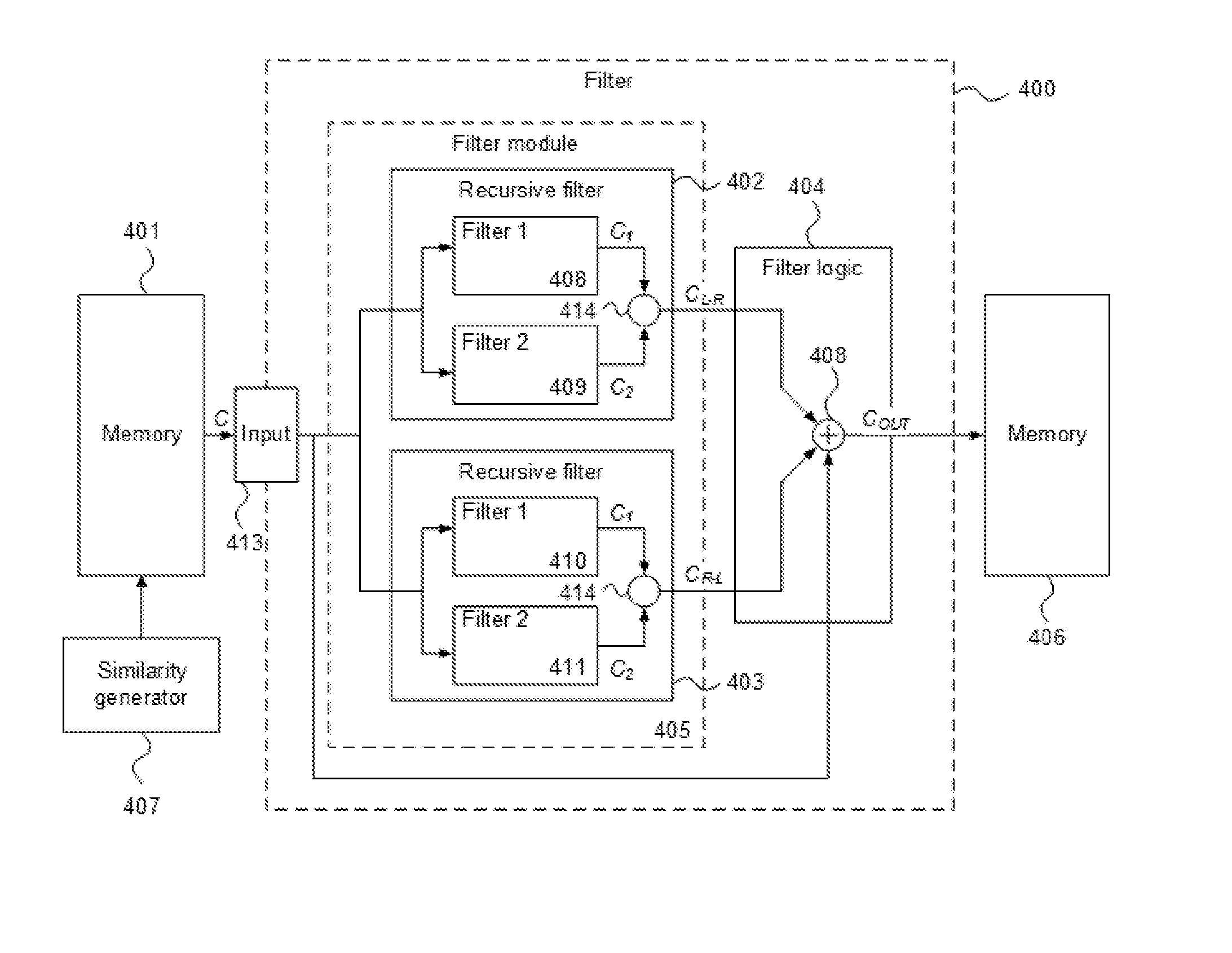
[0090]There is provided a filter and method for filtering pixels of a frame in a graphical processing system, particularly for filtering out the noise developed by path / ray tracing techniques, whilst maintaining acceptable image quality. The method described herein is especially suitable for filtering noise in a raster light map.

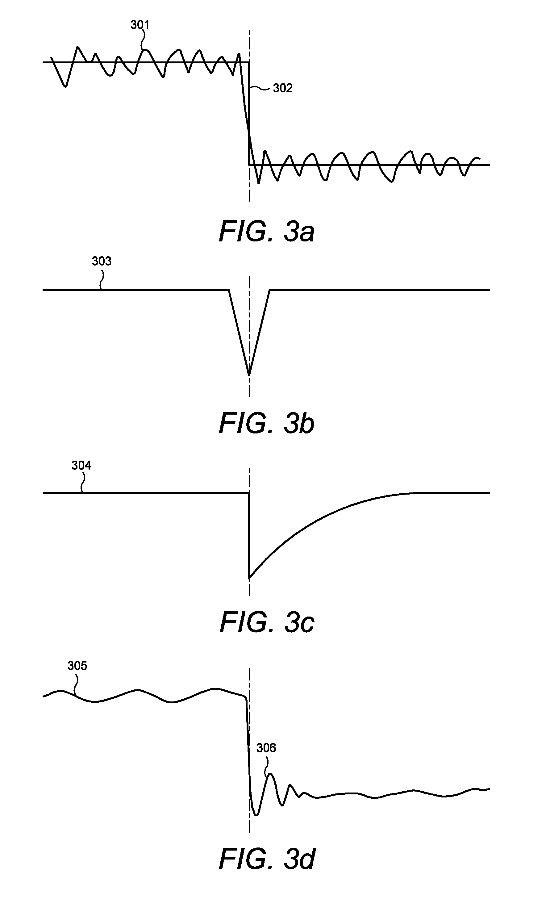
[0091]Noise in rendered images may be smoothed out through the use of a conventional filter, such as a bilateral filter. Such filters can provide good quality images but are computationally expensive. Path and ray tracing is itself computationally complex and it can be challenging to implement in real-time, even if a hybrid approach is adopted where...


PUM


Abstract

A pixel filter includes an input arranged to receive a sequence of pixels, each pixel having an associated pixel value; a filter module arranged to perform a first recursive filter operation in a first direction through the sequence of pixels so as to form a first filtered pixel value for each pixel, and perform a second recursive filter operation in a second direction through the sequence of pixels so as to form a second filtered pixel value for each pixel, wherein the first and second recursive filter operations form a respective filtered pixel value for a given pixel in dependence on the pixel value at that pixel and the filtered pixel value preceding that pixel in their respective direction of operation, the filtered pixel value of the preceding pixel being scaled by a measure of similarity between data associated with that pixel and its preceding pixel; and filter logic configured to, for each pixel of the sequence, combine the first and second filtered pixel values formed in respect of the pixel by the first and second recursive filter operations so as to generate a filter output for the pixel.

Description

BACKGROUND OF THE INVENTION[0001]This invention relates to a filter and method for filtering pixels of a frame in a graphical processing system, and in particular for filtering pixels in a frame rendered by path or ray tracing.[0002]Several techniques are available for rendering three-dimensional (3D) scenes for display on a computer system. These include scanline rendering into two dimensions of a scene described in the computer system in three dimensions, path tracing and ray tracing. Path tracing forms an image by determining the net colour arriving at each pixel of a frame defined at a particular viewpoint in a 3D scene. The net colour is calculated by integrating over the contributions from all of the light rays received at the pixel, including light rays which have been reflected (potentially multiple times) by surfaces in the scene. By defining physically accurate models of the surfaces and light sources in the scene, including the reflection characteristics of the surfaces, ...

Claims


Application Information

Patent Timeline
IPC IPC(8): G06T5/00G06T15/06G06T5/20
CPCG06T5/002G06T15/06G06T5/20
Inventor CSEFALVAY, SZABOLCS
Owner IMAGINATION TECH LTD
Why Eureka
Try Eureka