Device for harvesting energy from a fluidic flow including a thin film of piezoelectric material

a technology of fluidic flow and piezoelectric material, which is applied in the direction of piezoelectric/electrostrictive/magnetostrictive devices, piezoelectric/electrostriction/magnetostriction machines, electrical apparatus, etc., can solve the problems of high stiffness, risk of failure, and inability to optimize the amount of energy recovered

Active Publication Date: 2017-02-02
FOND INST ITAL DI TECH
View PDF13 Cites 24 Cited by
  • Summary
  • Abstract
  • Description
  • Claims
  • Application Information

AI Technical Summary

Problems solved by technology

However, in the case where the energy-harvesting system is immersed in a gas, the high stiffness does not enable optimization of the amount of energy recovered.
Thus, at present a PVDF layer with piezoelectric behaviour may not have a thickness of less than about tens of micrometers; otherwise, there is the risk of failure.

Method used


Image

  • Device for harvesting energy from a fluidic flow including a thin film of piezoelectric material
  • Device for harvesting energy from a fluidic flow including a thin film of piezoelectric material
  • Device for harvesting energy from a fluidic flow including a thin film of piezoelectric material

Examples


Embodiment Construction

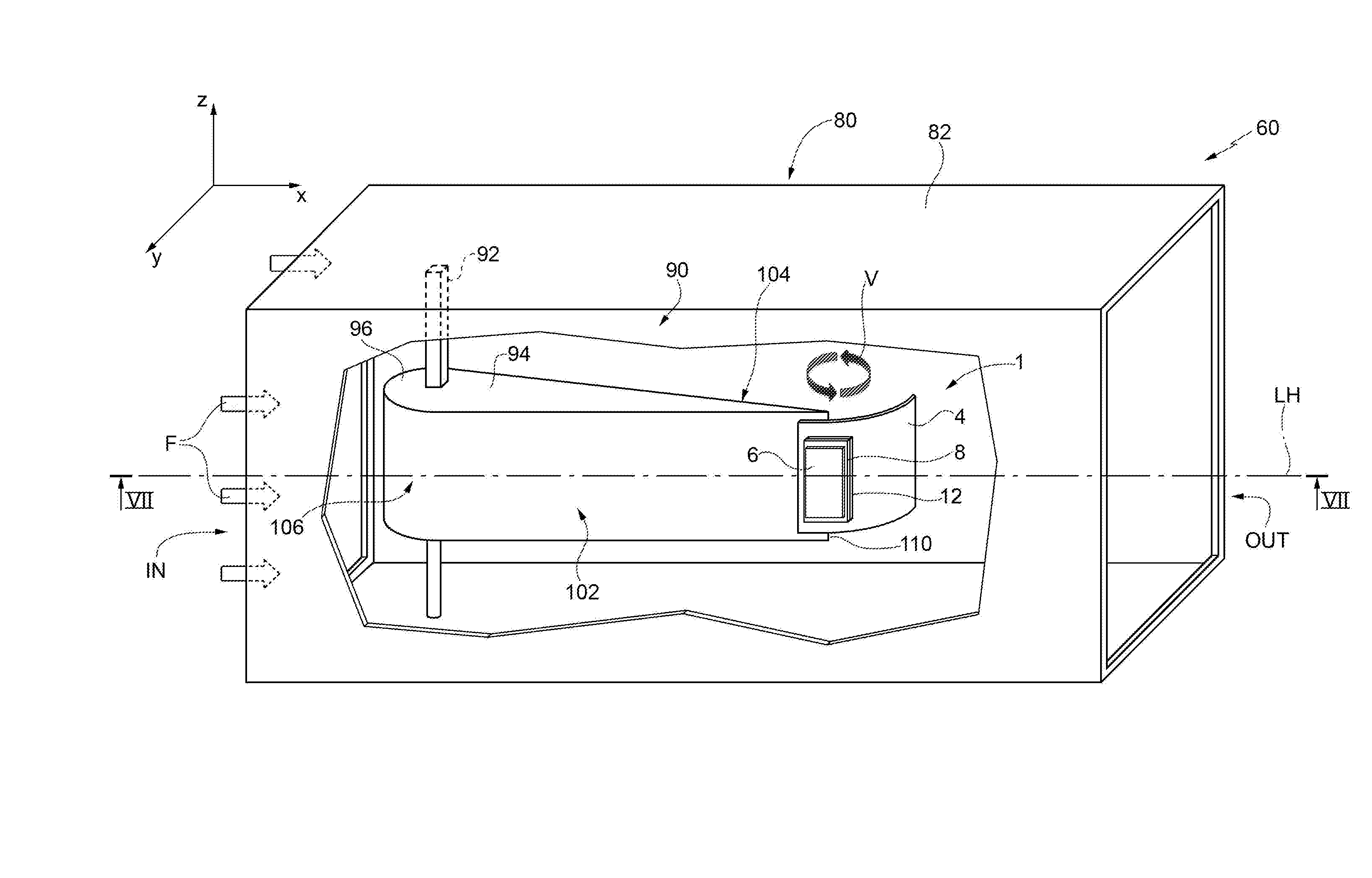
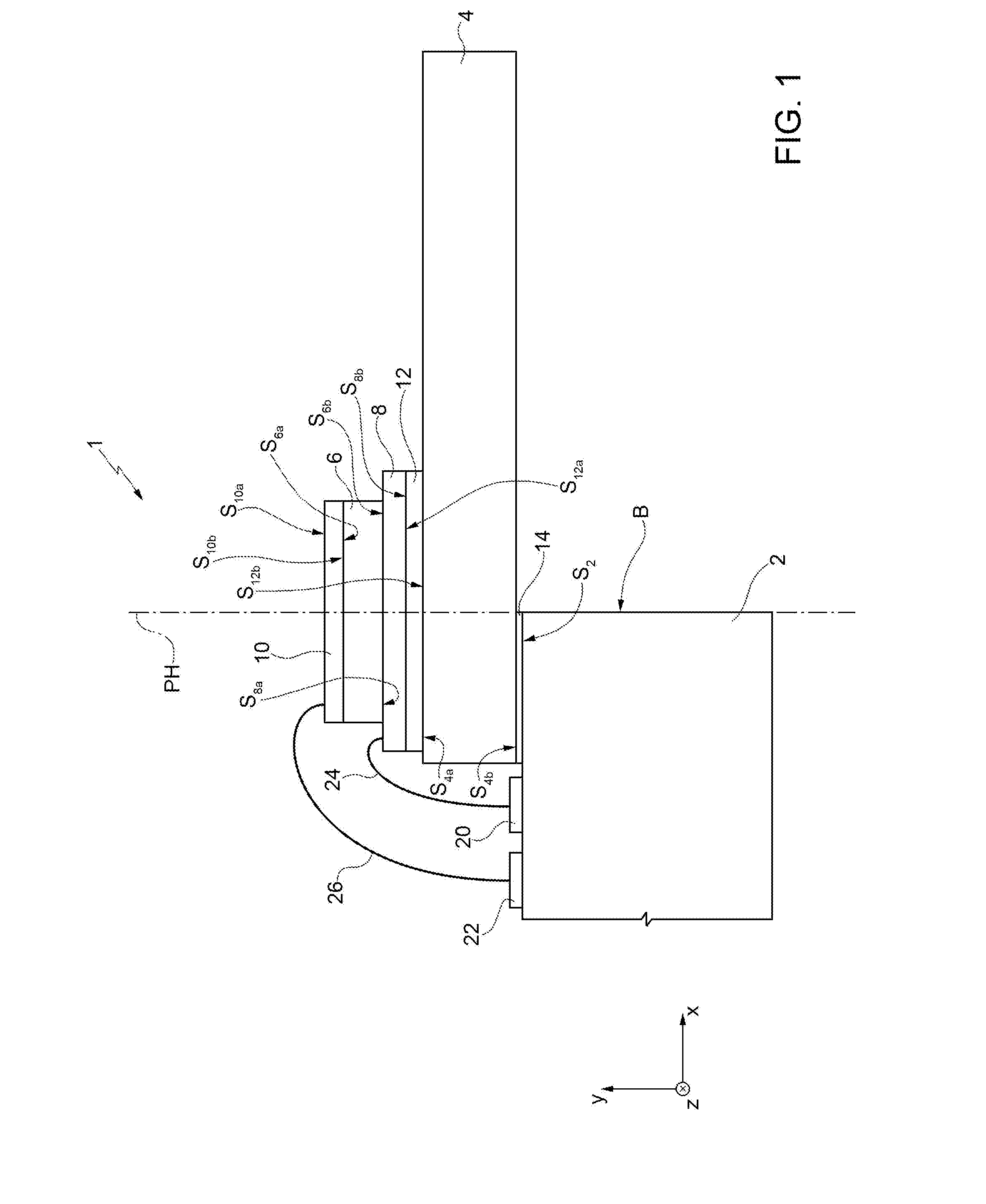
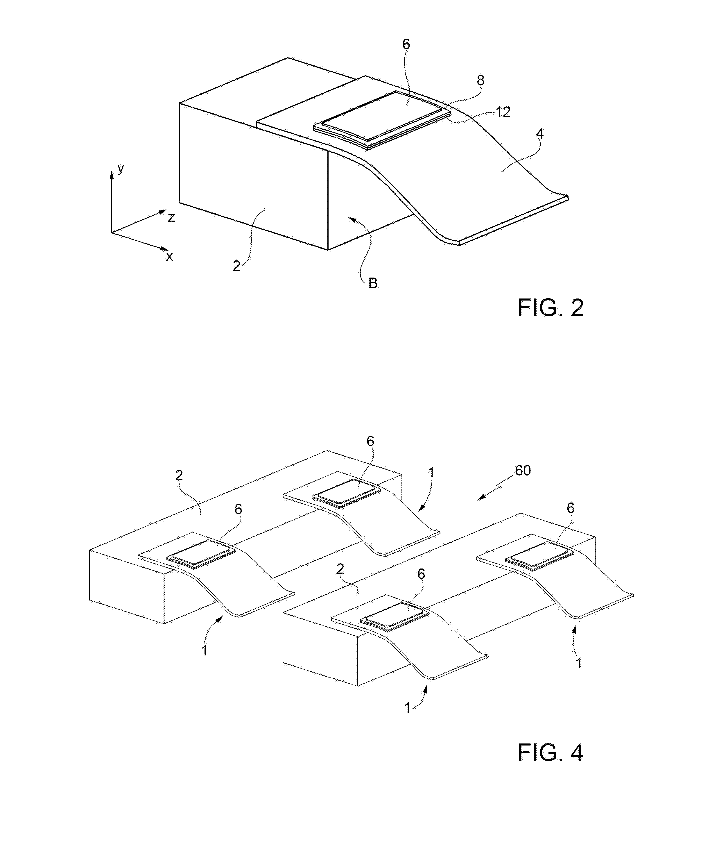
[0015]FIG. 1 shows an energy-harvesting device 1, which comprises: a supporting element 2 of a rigid type; a layer 4, referred to hereinafter as “flexible layer”4; a first piezoelectric layer 6; a first conductive layer 8 and a second conductive layer 10; a layer referred to hereinafter as “base layer” or “interlayer”12; and a bonding layer 14. In general, in the present description, the characteristics “flexible” and “rigid” of a given element are to be understood as referring to the capacity of this element to undergo dynamic deformation, or else not to undergo deformation, when the energy-harvesting device 1 is in use, i.e., when it is immersed, for example, in a flow of fluid having a rate of between 0.01 m / s and 20 m / s, as described hereinafter. In this connection, even though just the layer 4 is explicitly defined as flexible, also the first piezoelectric layer 6, the first and second conductive layers 8, 10, and the base layer 12 are flexible, i.e., deformable, and thus form ...


PUM


Abstract

A transmission belt is described which comprises a body made of a first elastomeric material, a plurality of teeth and a plurality of longitudinal cords buried in the body of the belt and a back. The belt has a working surface on said teeth and the working surface is at least partially covered by a covering made of a plastic and/or metal material. Defining the area comprised between the plane defined by the neutral axis of the cords, the working surface and the median transverse planes of two adjacent teeth as the unitary longitudinal section, the covering preferably occupies at least 25% of the unitary longitudinal section.

Description

TECHNICAL FIELD[0001]The present invention relates to a device for harvesting energy from a fluidic flow. In particular, the present invention regards a device including a thin film of piezoelectric material.BACKGROUND ART[0002]As is known, there are available today numerous types of energy-harvesting systems, which enable recovery of energy via a mechanical system driven by a natural element, such as, for example, wind.[0003]For instance, the U.S. Pat. No. 6,424,079, describes an energy-harvesting system, which comprises a flexible central layer, made of dielectric material, and a first layer and a second layer of piezoelectric material (polyvinylidene fluoride, PVDF). In addition, the energy-harvesting system forms a plurality of piezoelectric elements, electrically separated from one another, each of which is constituted by a pair of electrodes arranged on opposite sides of one between the first and second layers of piezoelectric material. The thickness of the central layer is co...

Claims


Application Information

Patent Timeline
Patent Type & Authority Applications(United States)
IPC IPC(8): H02N2/18H01L41/113H01L41/047H01L41/08
CPCH02N2/185H01L41/047H01L41/1136H01L41/0815H10N30/10516H10N30/306H10N30/87
Inventor PETRONI, SIMONARIZZI, FRANCESCOGUIDO, FRANCESCODE VITTORIO, MASSIMO
Owner FOND INST ITAL DI TECH
Why Eureka
Try Eureka