Method and apparatus for tracking uplink beam in beamforming-based cellular system

a beamforming-based cellular system and uplink beam technology, applied in the field of methods and apparatus for tracking uplink beams, can solve the problems of communication interruptions, take a long time to detect the best beam pair,

Inactive Publication Date: 2017-02-02
SAMSUNG ELECTRONICS CO LTD
View PDF7 Cites 64 Cited by
  • Summary
  • Abstract
  • Description
  • Claims
  • Application Information

AI Technical Summary

Problems solved by technology

However, it takes a long time to detect the best beam pair because of the physical constraint that the MS is not capable of measuring the received signal qualities of a plurality of beam pairs at one time.
This time delay may cause communication interruptions while the MS is searching for a new beam pair for a neighboring cell, when a handover event occurs along with movement of the MS from a serving cell to the neighboring cell.

Method used


Image

  • Method and apparatus for tracking uplink beam in beamforming-based cellular system
  • Method and apparatus for tracking uplink beam in beamforming-based cellular system
  • Method and apparatus for tracking uplink beam in beamforming-based cellular system

Examples


Embodiment Construction

[0031]Preferred embodiments of the present disclosure will be described in detail with reference to the attached drawings. A detailed description of known functions or constructions will be omitted lest it should obscure the subject matter of the present disclosure. Terms used herein are defined in consideration of functions according to the present disclosure and may be changed according to the intention of a user or an operator, or customs. Therefore, the definition should be made based on the comprehensive contents of the present disclosure.

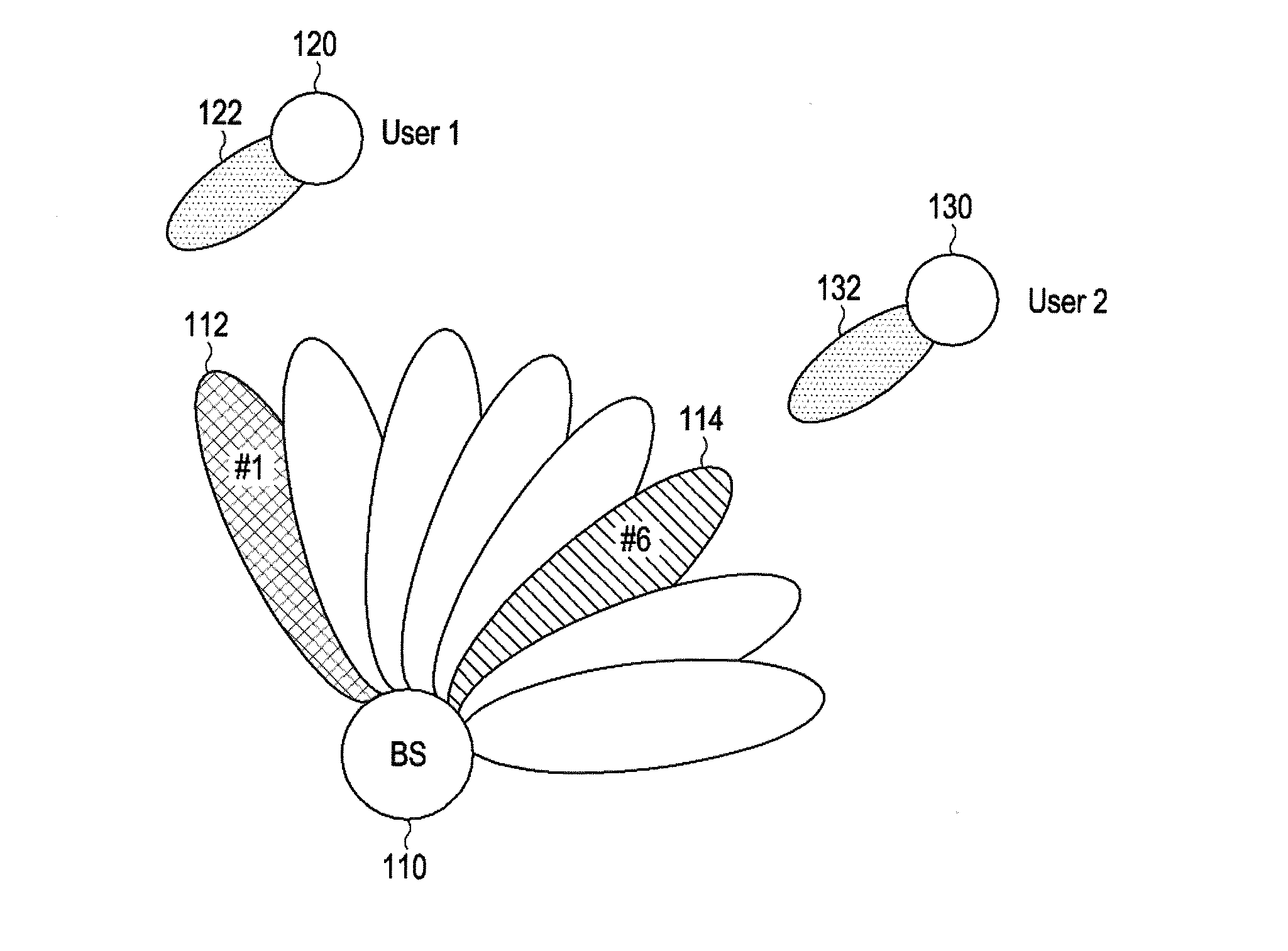
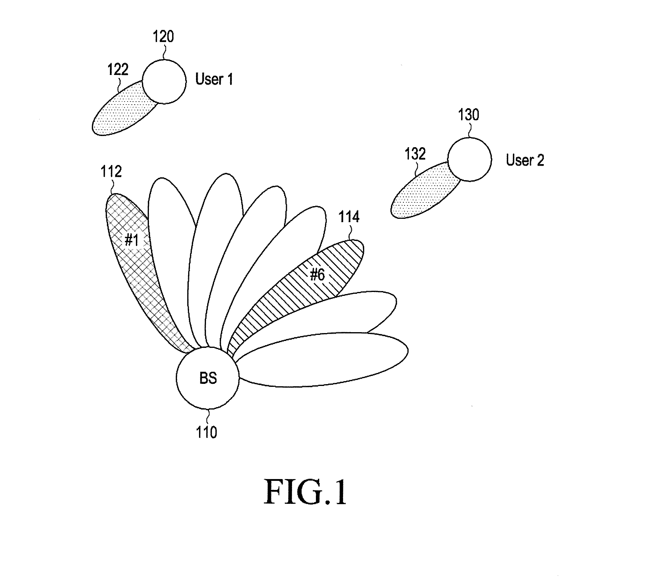
[0032]FIG. 1 illustrates an exemplary beamforming-based cellular system to which the present disclosure is applied.

[0033]Referring to FIG. 1, a base station (BS) 110 may serve mobile stations (MSs) 120 and 130 within a cell, using transmission antennas configured into an array antenna. The BS 110 forms beams for one or more scheduled MSs 120 and 130 by controlling a gain value for the direction (or channel) of each transmission antenna. In the...


PUM


Abstract

A method and an apparatus for tracking an uplink beam in a beamforming-based cellular system are disclosed. A method for a terminal comprises the steps of: transmitting, to a serving base station, a measurement report containing signal qualities of the serving base station and neighboring base stations; receiving, from the serving base station, uplink beam tracking information of at least one beam tracking target base station; transmitting an uplink beam training signal for the beam tracking target base station, on the basis of the uplink beam tracking information; and receiving, from the serving base station, information on an optimum terminal transmission beam of the beam tracking target base station, and storing the received information.

Description

TECHNICAL FIELD[0001]The present disclosure relates to a method and apparatus for tracking an uplink beam for efficient handover in a beamforming-based cellular system.BACKGROUND ART[0002]To satisfy demands for wireless data traffic, which have been increasing since commercialization of a 4th generation (4G) communication system, efforts have been made to develop a 5th generation (5G) or pre-5G communication system. That is why the 5G or pre-5G communication system is called a beyond 4G network communication system or a post long term evolution (LTE) system.[0003]To achieve high data rates, deployment of the 5G communication system in a millimeter wave (mmWave) band (for example, a 60-GHz band) is under consideration. In order to mitigate propagation path loss and increase a propagation distance in the mmWave band, beamforming, massive multiple input multiple output (MIMO), full dimensional MIMO (FD-MIMO), array antenna, analog beamforming, and large-scale antenna technology have be...

Claims


Application Information

Patent Timeline
Patent Type & Authority Applications(United States)
IPC IPC(8): H04B7/06H04W72/04H04L12/26
CPCH04B7/0617H04W72/0413H04L43/08H04W24/00H04W24/10H04B7/0404H04B7/0408H04B7/0695H04W36/08H04W36/30H04W36/38H04W36/00835H04W36/0085H04W72/21
Inventor YOO, HYUN-IL
Owner SAMSUNG ELECTRONICS CO LTD
Why Eureka
Try Eureka