Sensor assembly with selective infrared filter array

a technology of infrared filter array and sensor assembly, which is applied in the field of image sensors with selective infrared filter array, can solve the problems of difficult to accurately estimate the amount of infrared crosstalk, limited techniques, and less than the full dynamic range of visible pixel available for visible light alon

a technology of infrared filter array and sensor assembly, which is applied in the field of image sensors with selective infrared filter array, can solve the problems of difficult to accurately estimate the amount of infrared crosstalk, limited techniques, and less than the full dynamic range of visible pixel available for visible light alon

US20170034456A1Inactive Publication Date: 2017-02-02DUAL APERTURE INT

Image

  • Sensor assembly with selective infrared filter array
  • Sensor assembly with selective infrared filter array
  • Sensor assembly with selective infrared filter array

Examples


Embodiment Construction

[0030]The figures and the following description relate to preferred embodiments by way of illustration only. It should be noted that from the following discussion, alternative embodiments of the structures and methods disclosed herein will be readily recognized as viable alternatives that may be employed without departing from the principles of what is claimed.

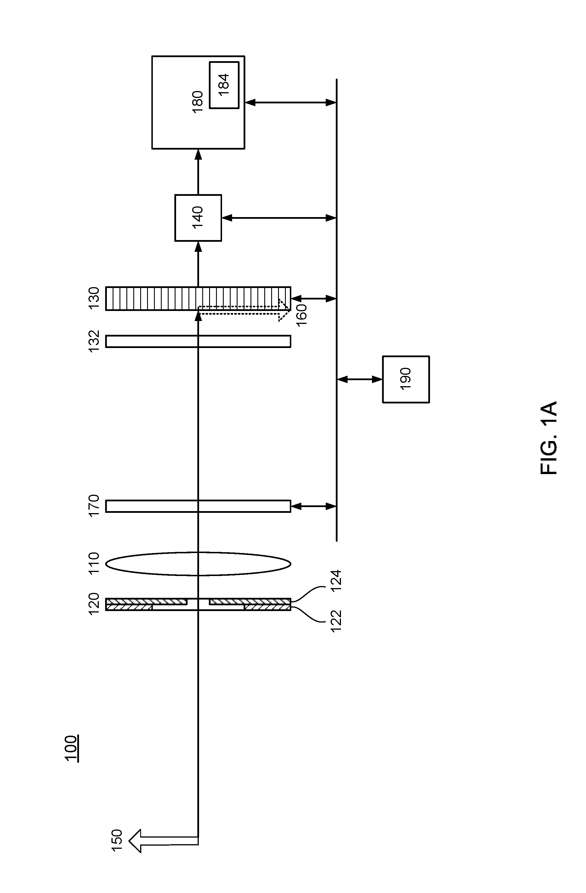
[0031]FIG. 1A is a block diagram of a multi-aperture, shared sensor imaging system using a sensor assembly according to one embodiment of the invention. The imaging system may be part of a digital camera or integrated in a mobile phone, a webcam, a biometric sensor, image scanner or any other multimedia device requiring image-capturing functionality. The system depicted in FIG. 1 includes imaging optics 110 (e.g., a lens and / or mirror system), a multi-aperture system 120 and an image sensor 130. The imaging optics 110 images objects 150 from a scene onto the image sensor 130. In FIG. 1, the object 150 is in focus, so that the ...


PUM


Abstract

An image sensor includes both visible pixels and infrared pixels. The visible pixels produce signals indicative of light within a visible band received by the visible pixels, and the infrared pixels produce signals indicative of light within an infrared band received by the infrared pixels. A selective infrared (SIR) filter array is integrated on the image sensor. The SIR filter array includes SIR pixel filters that are positioned to filter out light within the infrared band propagating to the visible pixels. In this way, infrared crosstalk to the visible pixels can be reduced.

Description

CROSS-REFERENCE TO RELATED APPLICATION(S)[0001]This application claims priority under 35 U.S.C. §119(e) to U.S. Provisional Patent Application Ser. No. 62 / 199,928, “Dual-band Camera” filed Jul. 31, 2015. The subject matter of all of the foregoing is incorporated herein by reference in its entirety.BACKGROUND[0002]1. Field of the Invention[0003]This disclosure relates generally to image sensors, and more particularly, to image sensors with selective infrared (SIR) filters, for example to reduce infrared leakage into visible pixels.[0004]2. Description of Related Art[0005]Image sensors have been widely used in digital cameras, mobile devices, security systems, computers, and many other applications. Some image sensors are designed to capture both visible (e.g., color) and infrared light. For example, some of the pixels in an image sensor may be used to convert visible light into electronic signals indicating color image information, and other pixels may be used to convert infrared lig...

Claims


Application Information

Patent Timeline
02 Feb 2017
Publication
US20170034456A1
IPC
H04N5/33; H04N5/238; G02B5/20; H04N5/225; H04N23/12; G03B11/00; G03B30/00; H04N23/75
CPC
H04N5/332; G02B5/208; H04N5/238; H04N5/2256; G03B11/00; H04N23/55; H04N23/11; H01L27/14621
Inventors
KYUNG, CHONG-MIN; CHOI, SANG GIL