Weed Seed Destruction

a technology of weed seed and weed seed, which is applied in the field of weed seed destruction, can solve the problems of large and complex cage mills, difficult to replace, and become resistant to herbicides, and achieve the effect of less damage potential and easy replacement every year

Active Publication Date: 2017-02-09
TRITANA INTPROP LTD
View PDF11 Cites 29 Cited by
  • Summary
  • Abstract
  • Description
  • Claims
  • Application Information

AI Technical Summary

Benefits of technology

[0057]To provide a seed destroyer in which the residue does not pass through rotating or stationary rings of objects so that there is less potential for damage on passage of a solid object.
[0058]To provide a seed destroyer in which the impacting members of the destructor can be hard surface coated and easily removable for annual replacement and preparation for the next harvest.

Problems solved by technology

In a number of areas of the world herbicides are used heavily to control the weed seeds however this has led to weed and grain seed that has become resistant to the herbicide.
However the cage mill shown is large and complex with numerous rings running in opposite directions.
Thus the system may function to destroy the seeds but has practical difficulties as it is without consideration of other obstacles passing through the assembly.
Although this is believed that this arrangement is closer to commercialization a number of problems remain with the design.
However it is a permanently fixed grinder without a means to bypass material other than residue.
This does not address seeds thrown over the back of the sieve and would not work if placed behind the sieve as today's combines the chaff stream is often 6 inches thick which would cushion the seeds and allow the spread of live seed back onto the field.
However this is not practical with today's combines.
The cart requires a second engine running in the dust of the combine and the mill requires a significant amount of power to pulverize and discharge the residue back onto the field.
The cage mill disclosed is large and complex with numerous rings running in opposite directions.
The cost of this system will limit its commercial viability.

Method used


Image

  • Weed Seed Destruction
  • Weed Seed Destruction
  • Weed Seed Destruction

Examples


Embodiment Construction

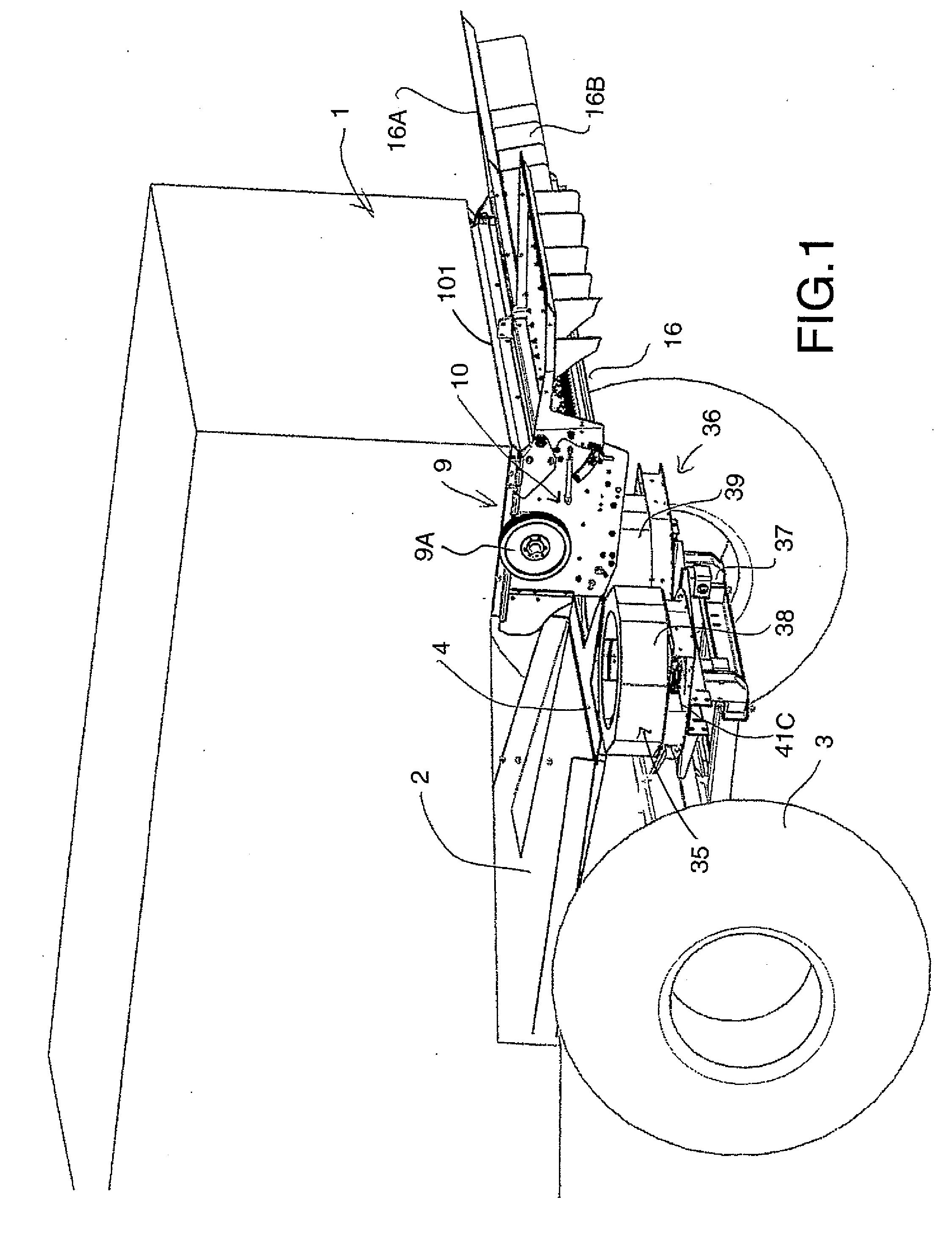
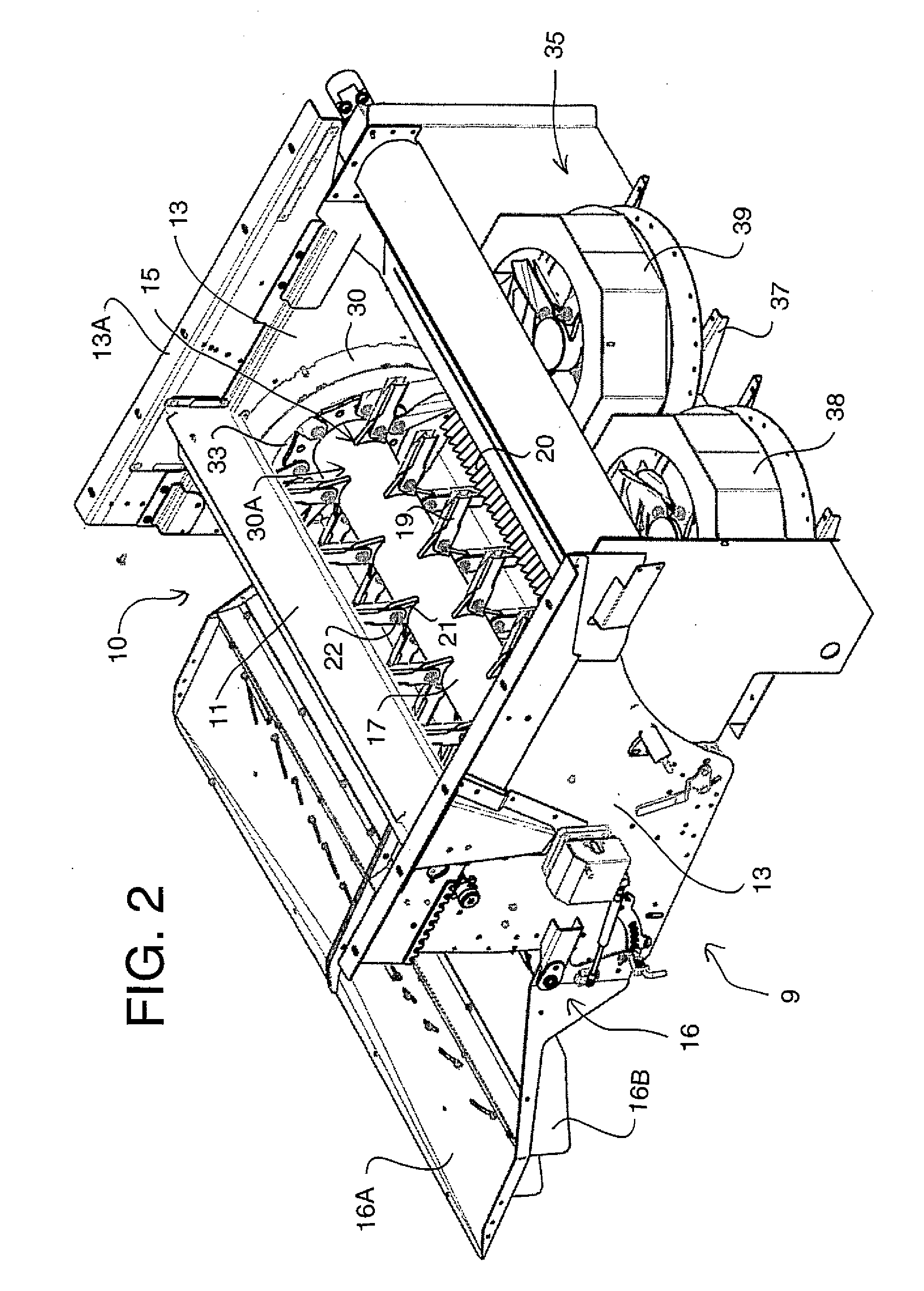
[0074]The apparatus herein is shown in FIG. 1 mounted on a combine harvester 1 carried on ground wheels 3 and including harvesting components of a conventional nature the rearmost one of which is the sieve 2 which discharges chaff and discarded seeds including weed seeds to the rear edge 4 of the sieve.

[0075]The combine harvester includes a chopper and discharge arrangement 9 shown in FIGS. 1 and 6 is basically as shown in U.S. Pat. No. 6,840,854 issued Jan. 11, 2005 of Redekop, the disclosure of which is incorporated herein by reference. The chopper thus comprises a housing 10 defined by a top wall 11, a bottom wall 12 and two end walls 13. The end walls 13 include attachment means 13A for attachment of the housing to the outlet of a combine harvester for discharge of straw and optionally chaff from the combine harvester into an inlet opening 15 of the housing 10. The bottom wall 12 defines a semi-cylindrical portion extending from the inlet 15 to an outlet 16 through which chopped...


PUM


Abstract

Weed seeds are destroyed in the chaff from a combine harvester by repeated high speed impacts caused by a rotor mounted in one of a pair of side by side housings which accelerate the discarded seeds in a direction centrifugally away from the rotor onto a stator including angularly adjustable stator surfaces around the axis. Thus the discarded seeds rebound back and forth between the rotor and the stator to provide a plurality of impacts. The seeds are carried axially of the rotor by a controlled airstream so that they move to an axial discharge location where a discharge fan is mounted. The angle of the discharge around the rotor axis can be changed to direct the seeds to the side of the combine away from a straw chopper, towards the guide fins of the tailboard of the chopper, or into the housing of the straw chopper.

Description

[0001]This application claims the benefit under 35 USC 119 (e) of Provisional application 62 / 192,111 filed Jul. 14, 2015.[0002]This invention relates to a weed seed destructor which can be attached to a combine harvester so that weed seeds in the discharged chaff can be devitalized before being spread onto the ground.BACKGROUND OF THE INVENTION[0003]Combine harvesters harvest cereal grain crops, such as wheat, oats, rye, barley, corn, soybeans and flax. Grain and straw are separated in a combine harvester. Following the separation process, waste straw and chaff is supplied to a chopper for shredding and distributing back over the field in an even spread pattern.[0004]During the harvesting process weed seeds and grain seed are discharged with the residue into the chopper and spread back onto the field. The combine is then effectively acting as a seeder to evenly spread the seed back onto the field. In a number of areas of the world herbicides are used heavily to control the weed seed...

Claims


Application Information

Patent Timeline
Patent Type & Authority Applications(United States)
IPC IPC(8): A01D41/12A01F12/48A01F7/06
CPCA01D41/1243A01F12/48A01F7/062A01F12/40
Inventor MAYERLE, DEAN
Owner TRITANA INTPROP LTD
Why Eureka
Try Eureka