
Medical tubes for breathing circuit

a technology of medical tubes and breathing circuits, applied in the field of tubes, can solve the problems of patients with very stiff lungs, inability to fully comply with the breathing circuit, and the performance of the breathing circuit and its components, so as to reduce the compressible volume of the breathing circuit, increase the amount of vapor, and increase the overall resistance to flow in the tube

Pending Publication Date: 2021-02-18
FISHER & PAYKEL HEALTHCARE LTD
View PDF0 Cites 0 Cited by
  • Summary
  • Abstract
  • Description
  • Claims
  • Application Information

AI Technical Summary

Benefits of technology

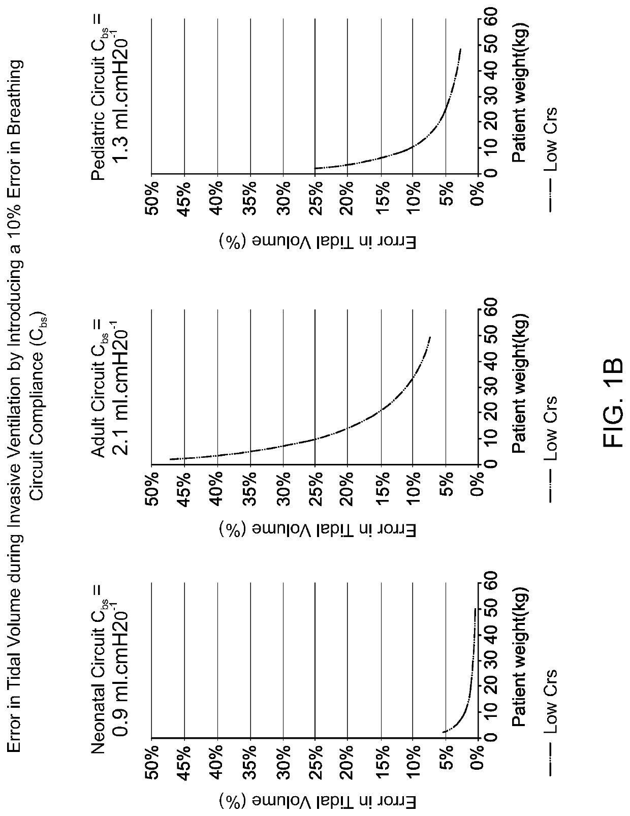
The present disclosure recognizes the need for improvements that can increase the removal of vapor from expiratory gases in an expiratory tube while reducing the compressible volume of a breathing circuit. This can be achieved by reducing the inner diameter of the inspiratory tube and increasing the inner diameter of the expiratory tube, which can increase the surface area of the walls and the cross-sectional area of the tubes. The reduction of compressible volume in the inspiratory tube can be due to a reduction in resistance to flow, while the increase in compressible volume in the expiratory tube can be due to increased surface area of the wall, diameter of the tube, cross-sectional area of the tube, or length of the walls of the expiratory tube. The increased compressible volume and resistance to flow in the expiratory tube can improve its permeability. The reduced compressible volume and resistance to flow in the inspiratory tube can maintain the same overall compressible volume and resistance to flow in the breathing circuit as a whole. The lower the compressible volume of a breathing circuit, the less potential there is for error in delivered tidal volume. A circuit kit for use in respiratory therapy for a patient can include a breathing circuit with these improvements.

Problems solved by technology

Using the combination of a smooth bore inspiratory tube with a corrugated expiratory tube has an unforeseen synergistic effect that improves performance of the breathing circuit and its components beyond expectations.
This is made worse by some lung disease states leading to patients with very stiff, low compliance lungs.
Additionally, a low compressible volume due to decrease in length (e.g. a shortened tube) is directly at odds with both usability and breathable expiratory limbs.

Method used


Image

  • Medical tubes for breathing circuit
  • Medical tubes for breathing circuit
  • Medical tubes for breathing circuit

Examples


Embodiment Construction

[0056]Breathing Circuit Comprising One or More Medical Tubes

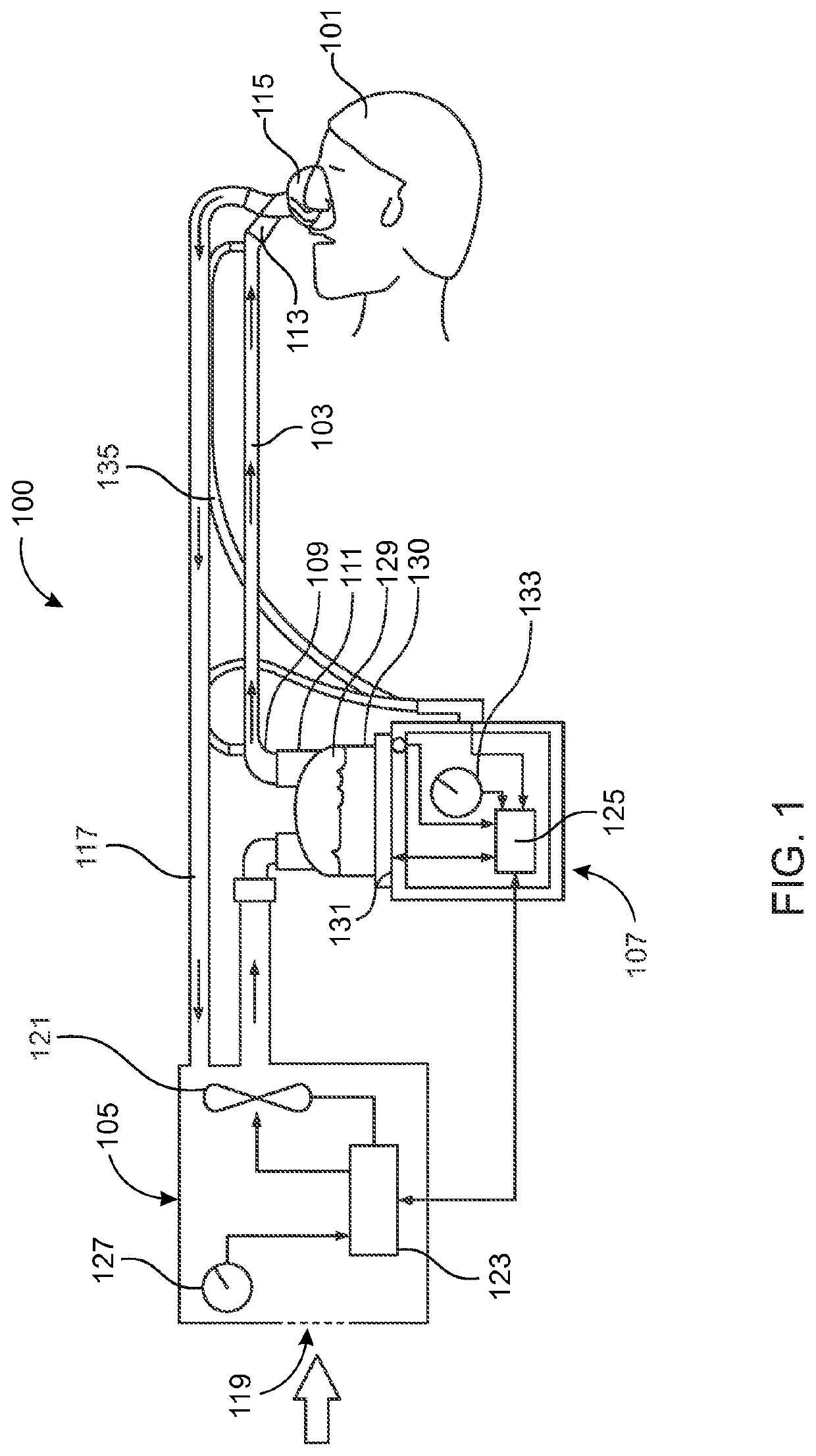
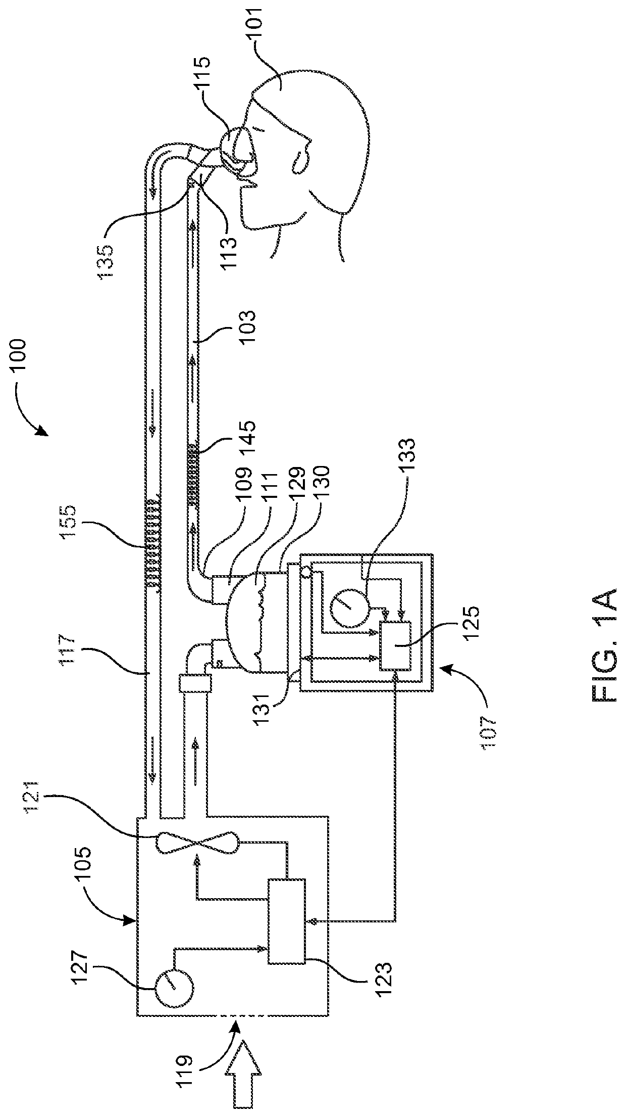
[0057]For a more detailed understanding of the disclosure, reference is first made to FIG. 1, which shows a breathing circuit 100. Such a breathing circuit 100 can be a respiratory humidification circuit. The breathing circuit 100 includes one or more medical tubes. The breathing circuit 100 can include an inspiratory tube 103 and an expiratory tube 117.

[0058]As used herein, medical tube is a broad term and is to be given its ordinary and customary meaning to a person of ordinary skill in the art (that is, it is not to be limited to a special or customized meaning) and includes, without limitation, cylindrical and non-cylindrical elongate shapes defining a lumen or comprising a passageway, such as a hollow, elongate body that are configured for use in medical procedures and that otherwise meet applicable standards for such uses. An inspiratory tube is a medical tube that is configured to deliver breathing gases to a patient...


PUM


Abstract

A breathing circuit for use in respiratory therapy includes an inspiratory tube and an expiratory tube. The inspiratory tube of the breathing circuit has a smooth bore. The expiratory tube of the breathing circuit is corrugated. Preferably, the expiratory tube is vapor permeable. Using the combination of a smooth bore inspiratory tube with a corrugated expiratory tube has the unexpected result of improving the performance of the breathing circuit and its components.

Description

INCORPORATION BY REFERENCE[0001]This application claims priority from U.S. provisional patent application Ser. No. 62 / 621,463 filed 24 Jan. 2018, the entire contents of which is hereby incorporated by reference in its entirety. This application is related to International Application No. PCT / NZ2017 / 050099 filed 21 Jul. 2017 and U.S. provisional patent application 62 / 365,285 filed 21 Jul. 2016, the entire contents of each is hereby incorporated by reference in its entirety. In addition, the disclosure below references various features of U.S. patent application Ser. No. 13 / 517,925, published as U.S. Patent Application Publication No. 2013 / 0098360 A1, U.S. patent application Ser. No. 14 / 123,485, published as U.S. Patent Application Publication No. 2014 / 0202462 A1, and U.S. patent application Ser. No. 14 / 649,801, published as U.S. Patent Application Publication No. 2015 / 0306333 A1. The entire disclosures of those applications and publications are hereby made part of this specification ...

Claims


Application Information

Patent Timeline
Patent Type & Authority Applications(United States)
IPC IPC(8): A61M16/08A61M16/16A61M16/10
CPCA61M16/0875A61M16/0883A61M16/0833A61M2240/00A61M16/1095A61M16/0808A61M16/16A61M16/00A61M2205/3327A61M2205/3368A61M16/08A61M16/1085A61M16/109A61M2205/3331A61M2205/7536
Inventor BUSWELL, MATTHEW LIAMMILLAR, GAVIN WALSHSTANTON, JAMES WILLIAM
Owner FISHER & PAYKEL HEALTHCARE LTD
Learn More