
Open end friction pile

a friction pile and open end technology, applied in bulkheads/piles, construction, foundation engineering, etc., can solve the problems of increased risk increased quality assurance checklists, and increased safety risks of ineffective strength testing or curing, so as to reduce manpower, reduce the number of inspection checklists, and simplify the quality assurance checklist

Active Publication Date: 2019-07-30
ALLENTOWN INFRASTRUCTURE GRP LLC
View PDF4 Cites 0 Cited by
  • Summary
  • Abstract
  • Description
  • Claims
  • Application Information

AI Technical Summary

Benefits of technology

The present invention has advantages such as a simplified quality assurance checklist, weather independence, soil penetration ability, faster installation speed, reduced manpower requirements, and effective resistance to load requirements. It can be installed in one working day with a minimum crew of three people and can be installed in any soil condition with minimal impact on the environment or cost.

Problems solved by technology

There is not a safety risk of ineffective strength tests or curing due to concrete transportation issues when project locations are away from commercial highways or roads.
When compared to concrete plants, chemical plants, mixing plants, and batch plants the excessive quality assurance checklists increase with each product movement.

Method used


Image

  • Open end friction pile
  • Open end friction pile
  • Open end friction pile

Examples


Embodiment Construction

[0050]The following discussion of the embodiments of the present invention it is to be understood that the invention can assume various alternative orientations. It is further understood that the invention is not limited to the application details since the invention is capable of alternative orientations.

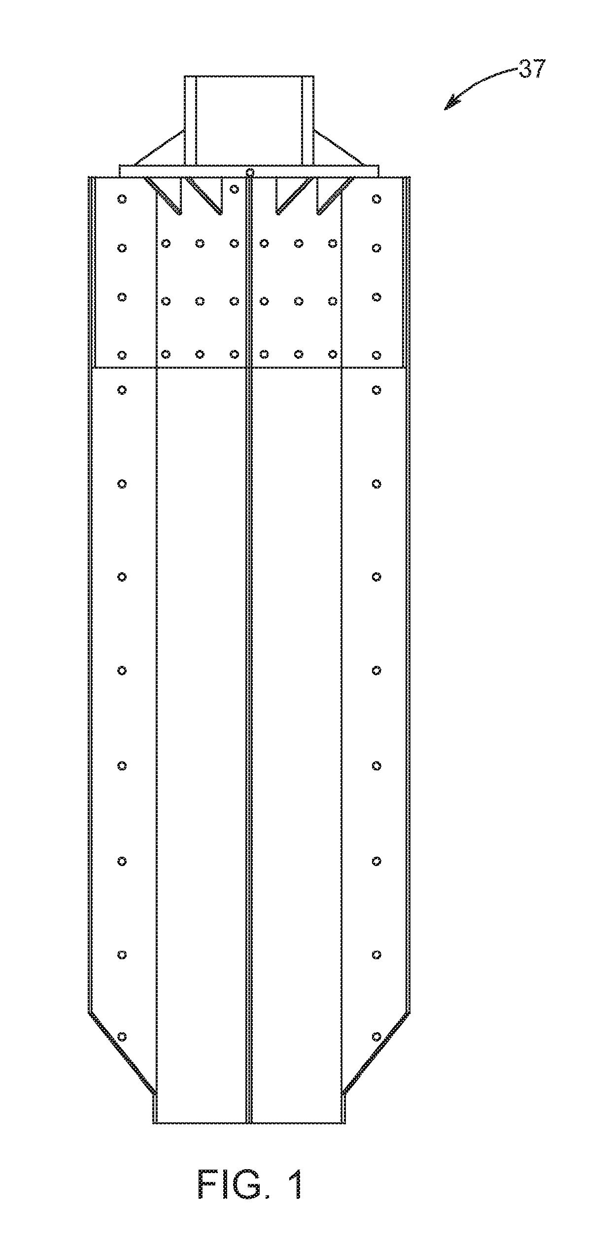
[0051]FIG. 1 illustrates the Open End Friction Pile 37 that pertains to tall commercial structures such as utility poles in the transmission industry and lattice towers in the cellular industry where the utility pole or lattice tower requires drilled reinforced concrete caissons to resist the load requirements based on applicable soil analysis.

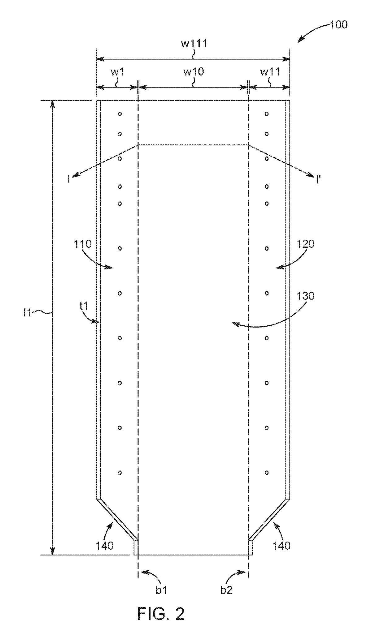
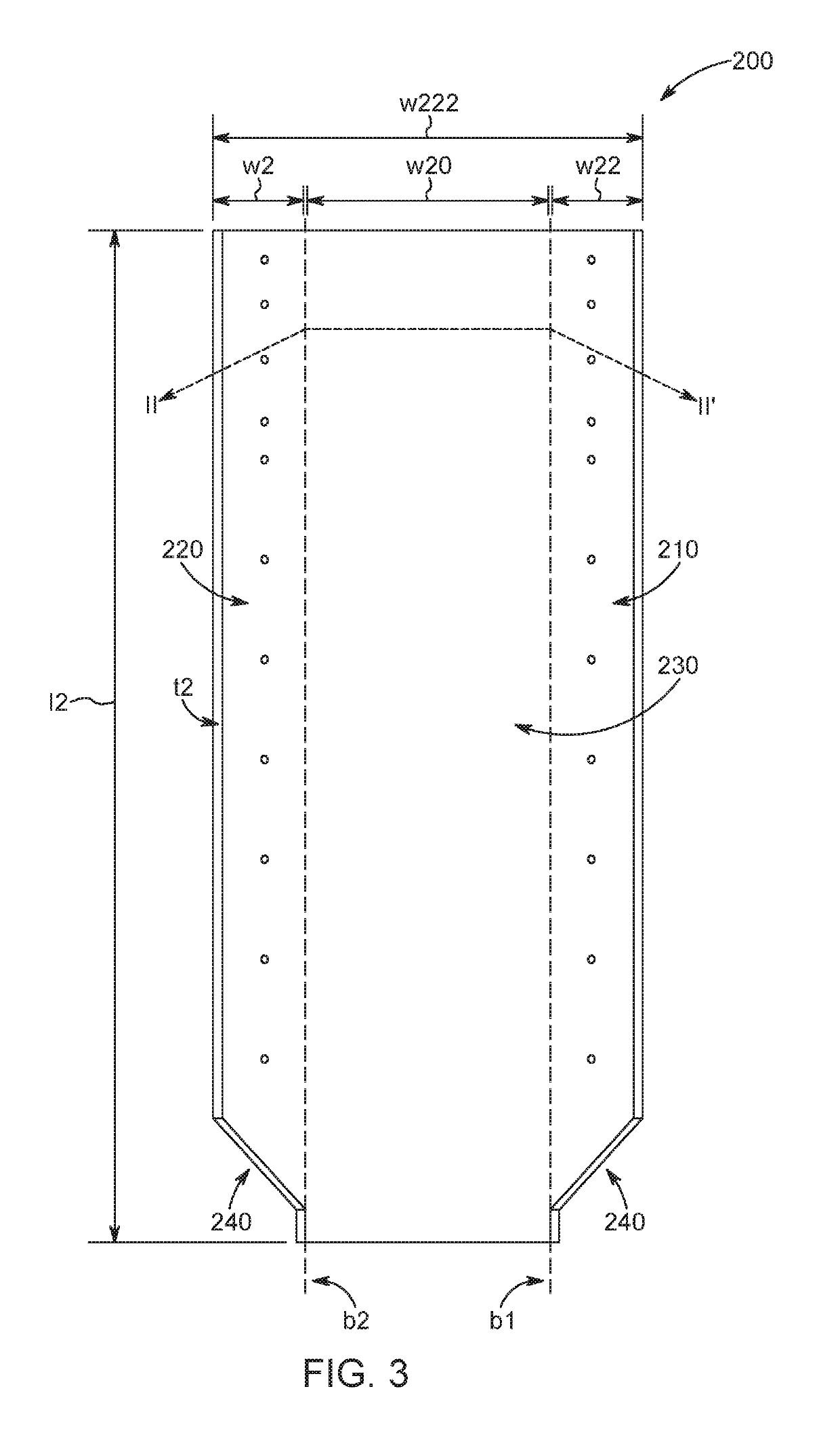
[0052]FIG. 2 illustrates the front view of steel plate 100 according to FIG. 1. The width w1 from the first bend line b1 from distal end 110 and the width w11 from the second bend line b2 from distal end 120 are equidistant. The width w10 of the center portion 130 of steel plate 100 is equal to the sum of the width of w1 and w11. At the botto...


PUM


Abstract

The Open End Friction Pile comprises of four steel plates, four brackets, and one driving head. The steel plates have a first bend line and a second bend line that are equidistant from a distal end. The first bend line and second bend line of the steel plates are equidistant from each other creating a center portion. The brackets have a first bend line and a second bend line that are equidistant from a distal end. The first bend line and second bend line of the brackets are equidistant from each other creating a center portion. The bracket has a third bend line along the center portion. One bracket is connected to one steel plate along the distal ends and center portion. All four steel plates and four brackets concurrently connect along the distal ends to form two open-ends. A driving head is connected covering the top open-end.

Description

BACKGROUND OF THE INVENTION[0001]The present invention pertains to supporting tall commercial structures. The present invention supports commercial structures such as utility poles in the transmission industry and lattice towers in the cellular industry. The present invention is an alternative solution to one or several reinforced drilled concrete caissons as supports for the pole or tower. A reinforced drilled concrete caisson is a foundation support to resist the load requirements of the pole or tower which is based on the applicable soil analysis. The load requirements are the various amounts of TONS that the pole or tower can withstand before it sinks, pulls out of the ground, falls over, or twists. A soil analysis is a boring log where an auger drills to a depth and core samples of the soil can be withdrawn for analysis. This analysis will determine if the soil is loose or dense, wet or dry, clay or sand, gravel-filled or impenetrable rock. Based on the load requirements and so...

Claims


Application Information

Patent Timeline
Patent Type & Authority Patents(United States)
IPC IPC(8): E02D5/22E02D5/28E02D7/06
CPCE02D5/223E02D5/285E02D7/06E02D2300/0032E02D2200/1642
Inventor KOMAN, TIFFANY LYNN
Owner ALLENTOWN INFRASTRUCTURE GRP LLC
Learn More