Overmolded body for bar feeder

a feeder body and overmolded technology, applied in the field of overmolded body feeders, can solve the problems of high assembly time, low yield, and low overall precision of guiding provided, and achieve the effect of improving the conferred anti-vibration and anti-noise properties and good density

Active Publication Date: 2021-08-31
LNS MANAGEMENT
View PDF13 Cites 0 Cited by
  • Summary
  • Abstract
  • Description
  • Claims
  • Application Information

AI Technical Summary

Benefits of technology

[0006]One object of the present invention is to propose a more efficient solution for production of a body for a bar feeder as well as for a body obtained by such a method in which the costs for production and labor are reduced.
[0009]One advantage of the proposed solution is that it achieves savings with respect to economy of scale as well as in terms of intrinsic production costs and in terms of labor.
[0010]Another advantage of the proposed solution is that it makes possible better guide features as well as better precision of assembly into bar feeder products, and this with a more homogeneous quality. In fact, the use of reusable molds and countermolds during the manufacture of each new bar feeder makes it possible to solve the problem of dimensional drift by ensuring the identical reproducibility of each new bar feeder, while improving their anti-vibration and anti-noise characteristics, and all of this without increasing their footprint.
[0011]According to a preferred embodiment, the proposed production method for a bar feeder body comprises a combined operation of molding and overmolding making it possible to achieve in an integral way a central assembly element constituting the said first structural and / or functional element because the latter replaces at the same time the usual beam and section in aluminum. Moreover, according to one preferred embodiment, the countermold constitutes just a frame to which other types of functional and / or structural elements can be grafted then detached, which are referred to as the “second” elements because they are made up of added mechanical pieces, such as, for example, anchoring elements as well as the structural frame element of the body or opening and closing rings of bearings as functional elements. In this case it is particularly easy to integrate these structural and / or functional elements achieved, for example, in metal in a way other than through fixation or through clamping or even by soldering or welding, but instead by a simple operation of overmolding such as claimed.
[0013]According to a preferred embodiment, the material used for the operation or operations of molding is preferably made up of concrete or polymer resin, the costs of which are relatively low and which have at the same time good properties of density and consequently make it possible to significantly improve the conferred anti-vibration and anti-noise properties while producing the desired structural and / or functional elements.

Problems solved by technology

One drawback of this assembly system is the dimensional drift during the assembly of each segment, one after the other, which is detrimental for the overall precision of the guiding provided for the bars.
On the other hand, assembly of the body turns out to be particularly tedious since for each machine it is necessary to assemble the guide channel segments one by one, which causes relatively high assembly times. Furthermore, apart from high labor costs, the costs of production are likewise quite high because the machining of the section used for the guiding and the beam of metal turn out to be expensive.
Finally, owing to the relatively low weight of the frame of the machine, the noises and the vibrations due to the rotation of the bar remain high and relatively irritating for those who need to work in the proximity of such a machine for prolonged periods of time.

Method used


Image

  • Overmolded body for bar feeder
  • Overmolded body for bar feeder
  • Overmolded body for bar feeder

Examples


Embodiment Construction

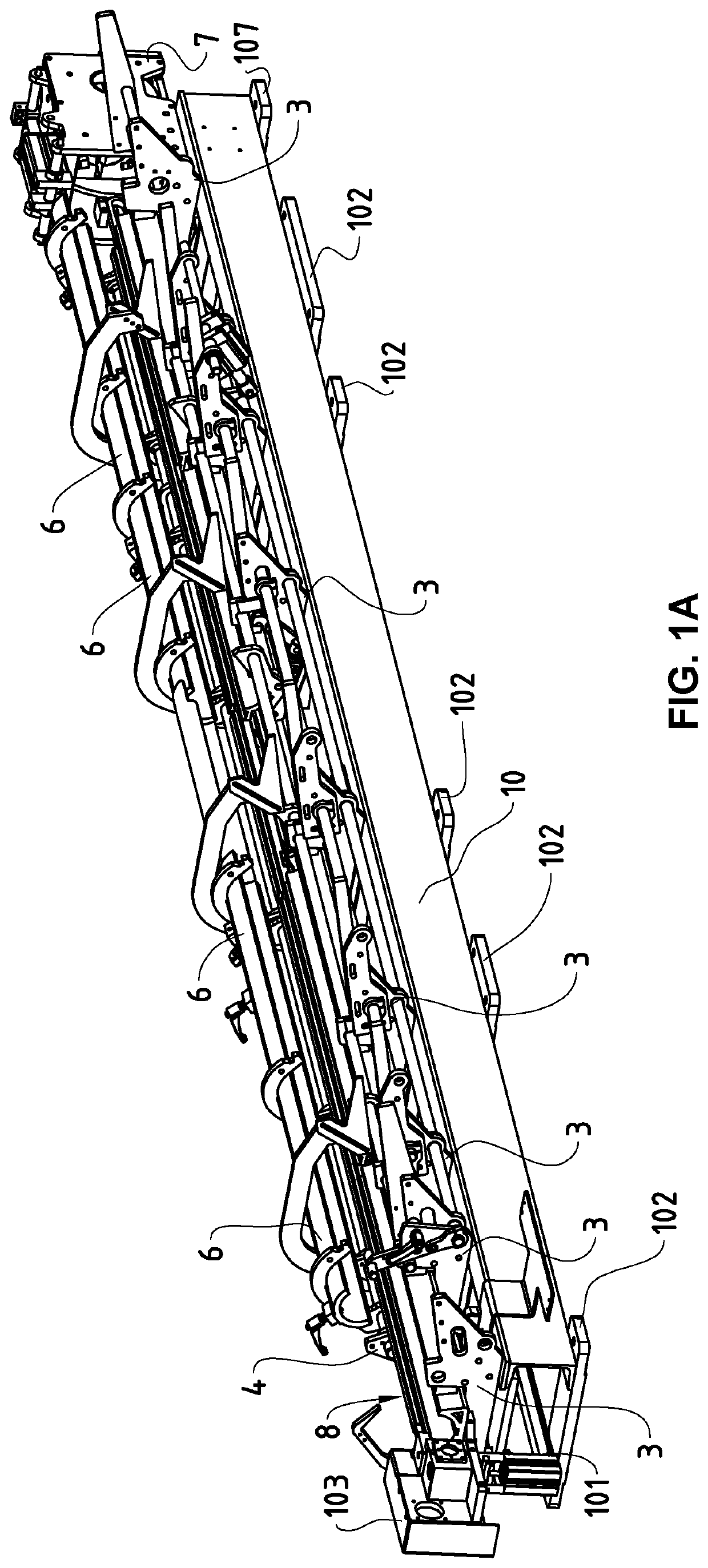
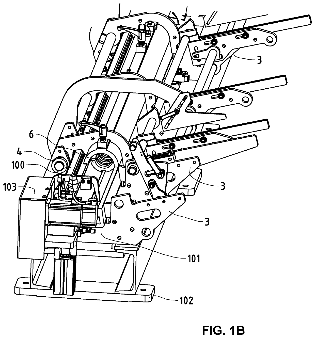
[0025]FIGS. 1A and 1B illustrate two schematic views in three dimensions of a bar feeder according to the prior art, mounted on a body constituted by a box 10 of metal, at the base of which are arranged fixation clamps 102 provided for assembly of the feet placed on the floor. The bar feeder is represented in two different functional positions, i.e. a first position (FIG. 1A) in which the bearings 6 are in open position, then a second position (FIG. 1B) in which the bearings 6 are closed. The structure of the body of this bar feeder is structured around a central beam of metal 100, visible in FIG. 1B, which is commonly referred to as “beam”, and to which are fixed different anchoring elements 3 and on which are mounted different segments of a section in aluminum 101 inside which are mounted the elements for guiding of the formed bars by the bearings 6. According to the disclosure illustrated in this figure, these bearings 6 are in fact constituted by two shells of identical shape, h...


PUM

PropertyMeasurementUnit
moldingaaaaaaaaaa
massaaaaaaaaaa
rigidityaaaaaaaaaa

Abstract

Method of producing a body (1) for bar feeders, wherein it comprises a first molding step (A) carried out with the aid of a first molding material (M1) in a mold (20) jointly with an overmolding step (B) of a countermold (50), the shape of the mold (20) and / or the shape impressions of the countermold being conceived to achieve in an integral way at least one structural and / or functional element of the said bar feeder.

Description

TECHNICAL FIELD OF THE INVENTION[0001]This invention relates to the field of bar feeders. More specifically, it concerns a method of producing a body, preferably made using polymer concrete, as well as a body obtained by such a production method for bar feeders.STATE OF THE ART[0002]The use of polymer concrete is known for machine tools as the filling material of hollow structures, permitting notably to increase the mass and to reinforce the rigidity, and also to damp the vibrations better during their use. The patent document EP1683602 describes such an example of a machine tool whose framework is partially filled with polymer concrete. No structural element nor even less so functional element, is made however using the polymer concrete whose purpose is merely to ballast and make rigid pre-existing structures.[0003]In the more specific context of bar feeders, intended, for example, to route bars to be machines by automatic lathes positioned downstream from the chain of production, ...

Claims


Application Information

Patent Timeline
Patent Type & Authority Patents(United States)
IPC IPC(8): B32B13/02B29C45/14B23B13/02B29C39/02B23B5/08B23B13/12B23Q7/04B29K103/08
CPCB29C45/14065B23B5/08B23B13/02B23B13/123B29C39/021B23Q7/042B29K2103/08B29C33/00
Inventor SCHENK, MARKREISSER, FRANK
Owner LNS MANAGEMENT
Why Eureka
Try Eureka